


11
LENS
DV
VIDEO OUT
TRGGER
REMORT
POWER
RGB
,
Y/C
,
SYNC
OUT
DC IN
SEE INSTRUCTION MANUAL
10
12
11
13
141516
17
0
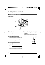
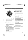
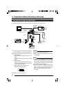
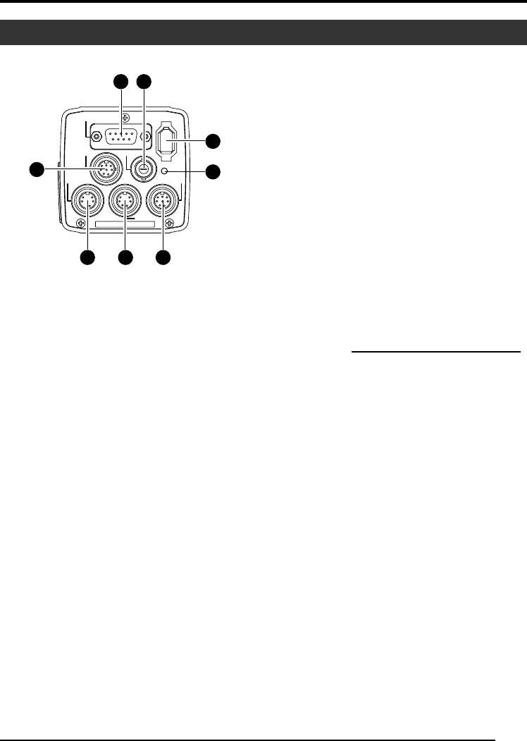
[RGB, Y/C, SYNC OUT] Analog
Output Terminal
Output terminal for R/G/B, Y/C and composite
video/sync signal.
☞Page 10 ‘9 Function Setting Switch’
☞Page 13 ‘Description of Terminals’
☞Page 48 ‘Connecting the analog output (D-
SUB) Cable’
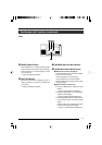
! [VIDEO OUT] Video Signal Output
Terminal
Output terminal for composite video signals.
Connect to video input terminals such as moni-
tors or switchers.
@ [DV] Digital Output Terminal
Digital output terminal for video. Connect this
terminal to computer’s [IEEE 1394] terminal or
[DV] terminal equipped video devices.
● If this terminal is to be used, set Switch 1 lo-
cated at the side of this unit to [ON].
● If this terminal is to be used to operate the
camera, set Switch 4 located at the side of
this unit to [ON].
☞Page 10 ‘9 Function Setting Switch’
☞Page 13 ‘Description of Terminals’
☞Page 48 ‘Connecting the IEEE 1394 Cable’
Part Names and Functions (continued)
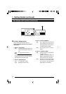
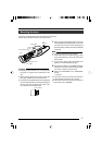
# [POWER] Power Indicator Light
Lights up when power is supplied to this unit.
$ [DC IN] Power Input Terminal
(Mini DIN 8 Pin, Female)
Power of this unit (DC 12 V) is supplied through
this terminal.
Use an AC adaptor (AA-P700) for the power sup-
ply.
☞Page 12 ‘Description of Terminals’
☞Page 18 ‘Connecting the Power Supply’
% [REMOTE] Remote Terminal
(Mini DIN 6 Pin, Female)
Terminal for connection to remote control unit
(RM-LP55 or RM-LP57, both sold separately).
☞Page 12 ‘Description of Terminals’
☞Page 46 ‘Connecting the Remote Control Unit’
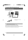
Caution
When using this unit as medical equipment, the
remote control unit (RM-LP55 or RM-LP57 sold
separately) cannot be used.
^ [TRIGGER] Trigger Terminal
(Mini DIN 5 Pin, Female)
For inputting and outputting the various types of
timing signal when Slow Shutter or Random Trig-
ger function is used.
☞Page 12 ‘Description of Terminals’
☞Page 49 ‘Technical Information’
& [LENS] Lens Connection Terminal
(Mini DIN 8 Pin, Female)
Connect the lens cable.
☞Page 12 ‘Description of Terminals’
☞Page 17 ‘Mounting the Lens’
Back