


16
ON
OFF
1234
2. Preparation Before Shooting (continued)
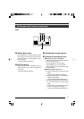
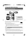
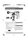
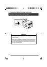
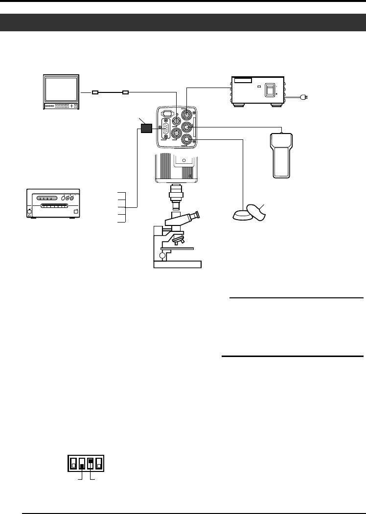
Connecting Through Analog Output
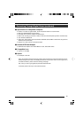
Caution
● Perform this when the devices are off.
● Use the 1/3-inch, C mount adapter for the micro-
scope adapter.
Notes
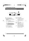
● Connect a switch between PIN 2 (TRIG) and PIN
3 (GND) of the [TRIGGER] terminal. If this switch
is set to [ON], a trigger will freeze the input image
to the camera and capturing of images synchro-
nized with the trigger is possible.
● Ensure to attach the supplied clamp filter to the
cable connected to the Analog Signal Output
[RGB, Y/C, SYNC OUT] terminal in order to re-
duce unwanted electromagnetic emissions.
☞ Page 48
Images taken by this unit can be output to monitor, color video printer or other devices.
1.
Connect device such as the Color Video Printer
to this unit’s [RGB, Y/C, SYNC OUT] terminal.
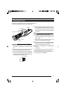
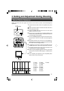
2.
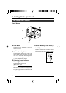
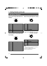
Set the switches located at the side of this unit.
● Setting Switch 2
Set this switch to [ON] (upper side) for Y/C
output.
Set this switch to [OFF] (lower side) for RGB
output.
● Setting Switch 3
Set this switch to [ON] (upper side) if sync sig-
nal is to be superimposed onto the Green (G)
channel of the video signal.
☞Page 10 ‘9 Function Setting Switch’
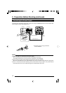
Example: During RGB output
3.
Switch on the power of this unit.
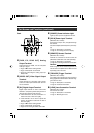
Trigger Switch
AC Adapter
[TRIGGER]
[REMOTE]
Switch 3Switch 2
AC ADAPTER AA-P700
AC ADAPTER AA-P700
ON
ON
OFF
OFF
POWER
POWER
POWER
POWER
ALARM
ALARM
SHEET
SHEET
PAPER
PAPER
DATA
DATA
OPEN
OPEN
CP700DSA
CP700DSA
MITSUBISHI
MITSUBISHI
ONLINE
ONLINE
COPY
COPY
& CUT
& CUT
PAPER FEED
PAPER FEED
]
LENS
DV
VIDEO OUT
TRGGER
REMORT
POWER
RGB
,
Y/C
,
SYNC
OUT
DC IN
SEE INSTRUCTION MANUAL
SETMENU
Microscope
Adapter
‘Connecting the
Power Supply’
(Page 18)
Color Video Printer etc.
Monitor
REMOTE
CONTROL
UNIT
RM-LP55
RM-LP57
BNC CABLE
AA-P700
[DC IN]
[VIDEO OUT]
[RGB, Y/C, SYNC OUT]
VC-451-2
R
G/Y
B/C
SYNC
VBS
Clamp filter
(accessories)
AC IN