


13
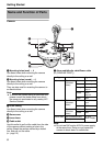
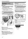
Alarm Input
Connect the cable to sensors such as infrared
sensors, door sensors, metal sensors and
manual switches.
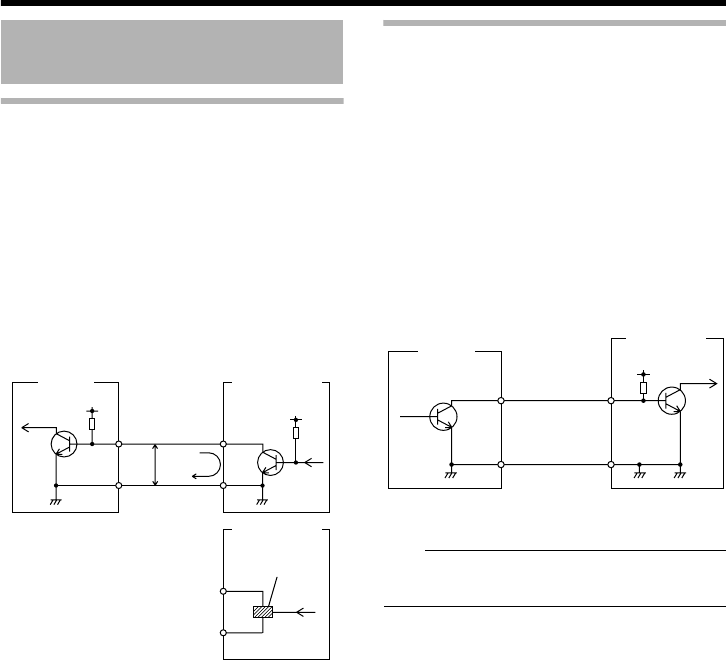
Ⅵ Input Requirements
● Non-voltage relay NPN open collector input
● Polarity of input detection can be selected
using a software
● Make/break (500 ms and above)
● Circuit current of 1 mA during low-level input
● Applied voltage of 3.3 V during high-level
input
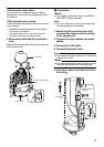
Alarm output
Connect to alarm devices such as alarm,
indicator, light or buzzer.
Ⅵ Output Requirements
● NPN open collector output equivalent (Refer
to the INSTRUCTIONS (Setting) on
procedures to set the output logic. )
● Allowable applied voltage: DC 12 V and
below
● Allowable inflow current: 50 mA
● Momentary (100 ms to 5000 ms) output
(Refer to [INSTRUCTIONS (Setting)] for
procedures to set the time. )
Note:
● Connect the GND cable of the camera to the
GND terminal of the alarm device.
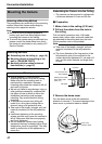
Connecting the Alarm
Input/Output Cable
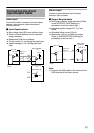
DC3.3 V
R
3.3 V1mA
VCC
OUT
GND
GND
OUT
R
GND
(Alarm input equivalent
circuit)
Input 1 or
Input 2
This unit
Sensor example
(1)
Sensor example
(2)
Relay switch, etc.
IN
R
DC 12 V
GND
GND
Alarm device
(example)
This unit
(Alarm output equivalent
circuit)
Output 1 or
Output 2