


6
Getting Started
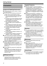
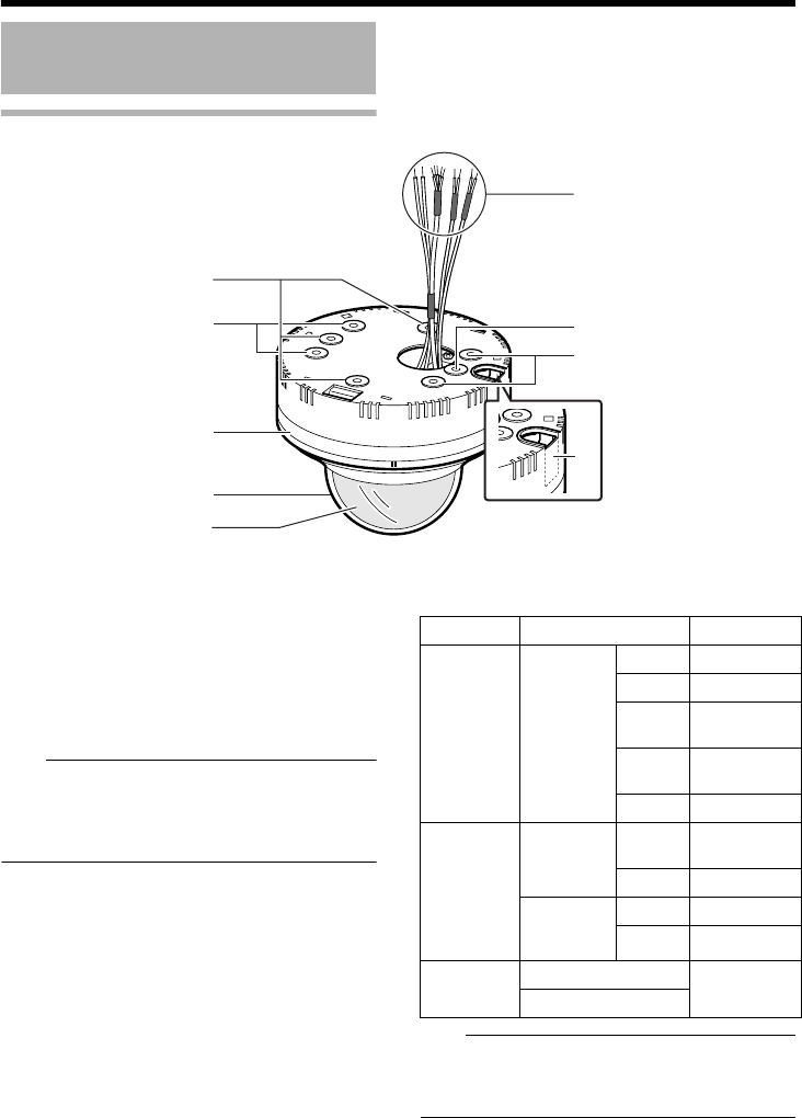
Camera
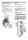
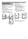
A
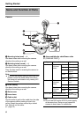
Mounting holes (oval) ן 4
Use these holes when mounting the camera
directly to the ceiling or a wall.
B Mounting holes (round) ן 4
Use these holes when mounting the camera
directly to the ceiling or a wall.
They are also used for mounting the camera to
an electrical box.
Note:
● To mount the camera using an electrical box,
please consult the dealer shop from which
the camera is purchased or any nearby JVC
Service Centers.
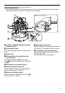
C Outer casing
Use these holes when mounting the camera
directly to the ceiling or a wall.
D Dome cover
E Inner dome
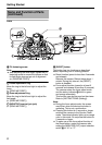
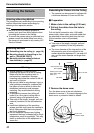
F Cable outlet
Use this outlet to pull out the cable from the side
of the camera without making a hole in the
ceiling. Break the section marked by a dotted
line, and pull out the cable.
(A page 12)
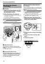
G Alarm cable/Audio cable/Power cable
(A [READ ME FIRST])
Note:
● Do not use PoE and an AC24 V power supply
at the same time. Doing so may cause the
camera to break down or malfunction.
Name and Function of Parts
B
D
C
A
E
A
B
F
G
Type Color Signal name
Alarm cable Black
(Shielded
cable)
Red Alarm input 1
Brown Alarm input 2
Orange Alarm
output 1
Yellow Alarm
output 2
Black GND
Audio cable Pink
(Shielded
cable)
White Microphone
input
Yellow GND
Black
(Shielded
cable)
White Line output
Yellow GND
Power cable
Red (Unshielded cable)
AC 24 V
Power Supply
Black (Unshielded cable)