


6
Operating Precautions (continued)
● The white balance (ATW) of this device is optimally set for sunlight.
Proper white balance may not be achieved for artificial lighting such
as fluorescent lighting, etc.
● If you use this camera in locations where the camera is exposed to
fluorescent light, a slow color change may occur.
(White balance normal = 5,400 K, range is 2,500 K to 10,000 K.)
● AGC HIGH(×2) and up: in this mode, ATW white balance may be
inaccurate.
● White balance performance decreases under poor lighting condi-
tions.
● Observe the following when carrying out camera maintenance.
•Turn the power OFF before proceeding to carry out maintenance.
If it is contaminated seriously, clean the contaminated part with a
cloth (or a tissue) which has been soaked in a solution of water and
a neutral detergent.
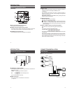
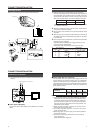
● The unit is to be powered by a DC 12 V or an AC 24 V power supply.
The AC 24 V power supply should conform to the following:
U type : Class 2 only
E type : Isolated power supply only
● The beat may sometimes appear on the screen if gain is raised
when the line lock is in use, but the phenomenon takes place due to
the fluctuation of power frequency and is not a malfunction.
● At Low light levels, video iris lens may “Hunt”. Please adjust iris
level on lens to minimise hunting.
● Recommended range of operating temperature is 0°C to 35°C de-
grees. The camera will function outside these parameters to –10°C
to 50°C degrees. But processing errors may be apparent.
● Line-Lock is set for 50 Hz ±0.02 Hz. If line frequency is outside this
tolerance, picture may jitter and some interference may be visible in
high contrast scenes.
● At low light level, when the slow shutter functions the screen may be
tinted.
INTRODUCTION
7
● Blemishes: Small spots are normal, the camera contains compen-
sation functions for blemishes above 120 mV (p-p) in value. Please
contact your JVC authorised dealer for further information.
● For temperatures higher than the recommended temperature, the
slow shutter may not work correctly.
8
INTRODUCTION
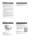
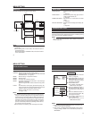
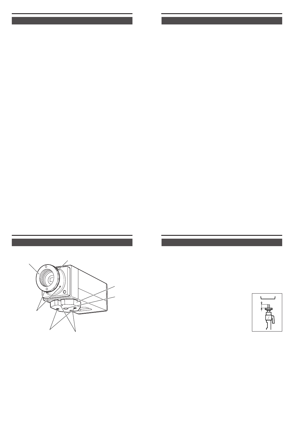
Names and Operations of Parts
[Front and Bottom]
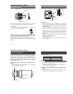
1 Lens mount
For use with CS mount lens.
(C-mount lenses require a conversion ring.)
2 Backfocus adjustment ring
Adjusting the back focus during lens installation.
Please refer to “Back focus adjustment” on ੬ Page 22 for instruc-
tions on how to adjust the back focus.
3
1
2
4
5
6
7
9
3 [BF LOCK] Back focus locking screw (× 2: 2 mm)
This serves to fix the back focus-adjusting ring.
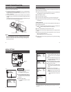
4 Camera-mounting bracket
The bracket has been attached on the bottom of the camera before
shipment. It can also be attached on the top according to the cir-
cumstance.
To re-attach the bracket use the threaded holes at the top, with the
camera mounting bracket locking screws 7.
5 Camera-mounting screw hole (1/4 inch)
Use this hole when mounting the camera
onto a fixer, pan/tilt unit, and the like.
(Use a screw shorter than 7 mm.)
(੬ Page 18)
6 Rotation prevention hole
Make use of this rotation-preventive hole to prevent any fall when
mounting the camera. Make sure that the camera is securely
mounted.
7 Camera mounting bracket fixing screws (× 2: M2.6 × 6 mm)
Be sure to use a 6 mm long screw.
MAX.
7mm