


10
Names and Operations of Parts
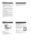
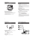
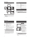
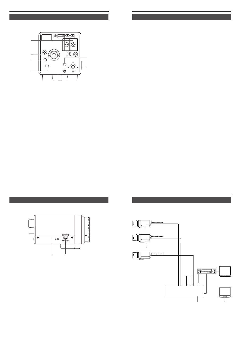
[Rear Panel]
SEE INST-
RUCTION
MANUAL
DC12V
AC24V
1
2
CLASS 2 ONLY (U TYPE)
ISOLATED POWER ONLY
(E TYPE)
POWER
VIDEO OUT
INT
LL
SET
SELECTOR
8 [DC 12V, AC 24V] Power input terminals
To input DC 12V or AC 24V power.
9 [VIDEO OUT] Video signal output connector
This BNC connector outputs a composite video signal. Connect this
to the video input connector of a video monitor, switcher, etc.
0 [POWER] Power indicator lamp
This lamp lights when power is supplied to the camera.
INTRODUCTION
A
B
8
9
C
0
11
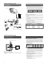
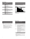
A [SET] button
During normal screen display, pressing and holding this button for
more than 2 seconds will display the MENU screen.
(੬ Page 24)
During MENU screen display, this button is pressed to display or
enable the selected menu item. The input digit will change when
entering the camera title.
When selecting EXIT in the TOP MENU screen, pressing this button
will return to the normal screen.
B [SELECTOR] button
Used when performing menu settings.
This button is a multidirectional switch.
Ⅵ Pressing in a vertical direction (6 or 7) will select the menu item.
Ⅵ Pressing in a horizontal direction (8 or t) will change the set
value of the item. When entering the camera title, the input char-
acter will change.
C [INT/ LL] Selector Switch for Synchronizing System
This switch can set a synchronizing system of the camera.
INT:
This is set for internal synchronization (INT) .
LL (Line Lock): U type: 60Hz power region only
E type: 50Hz power region only
The camera’s vertical synchronization is locked to the AC 24V power
line frequency.
When switching between multiple cameras using a switcher, select-
ing this mode and adjusting the vertical phase can reduce the moni-
tor sync disturbances occurring when the camera image is switched.
(INT: At time of factory shipment)
12
Names and Operations of Parts
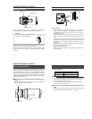
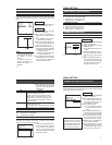
[Side Panel]
COLOR VIDEO CAMERA
IRIS
DC
VIDEO
D [VIDEO/DC] Iris Selector Switch
This should be set according to the type of lens if an automatic iris
control lens is used.
VIDEO : In case of lens with EE amp built-in.
(੬ Page 20)
DC : In case of lens without EE amp built-in.
(੬ Page 14)
(DC : At time of factory shipment)
E [IRIS] Iris Terminal
This is connected to an automatic iris control lens.
(੬ Page 15)
INTRODUCTION
D
E
13
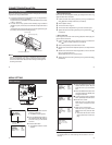
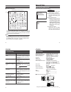
Basic System
Ⅵ System with up to 8 cameras
REC
PLAY
FFREW
REVERSE
PAUSE/
STILL
REC
CHECK
STOP/EJECT
COUNT/
CLOCK
TIME
MODE
TIMER
REC
AL/PL
RESET
MENU
VIDEO CASSETTE RECORDER
SHIFT/TRACKING
SET/V.LOCK
RESET
/CANCEL
OPERATE
SR-L910
OPE. LOCK
• •••••
COLOR VIDEO CAMERA
ALC
LEVEL
Av Pk
L H
COLOR VIDEO CAMERA
ALC
LEVEL
Av Pk
L H
COLOR VIDEO CAMERA
ALC
LEVEL
Av Pk
L H
Switcher
Video signal cable
Power
cable
AC24V or
DC12V
AC24V or
DC12V
AC24V or
DC12V
Camera 1
Camera 2
Camera 8
Monitor
Monitor
DVR, etc.
CONNECTION/INSTALLATION