


18
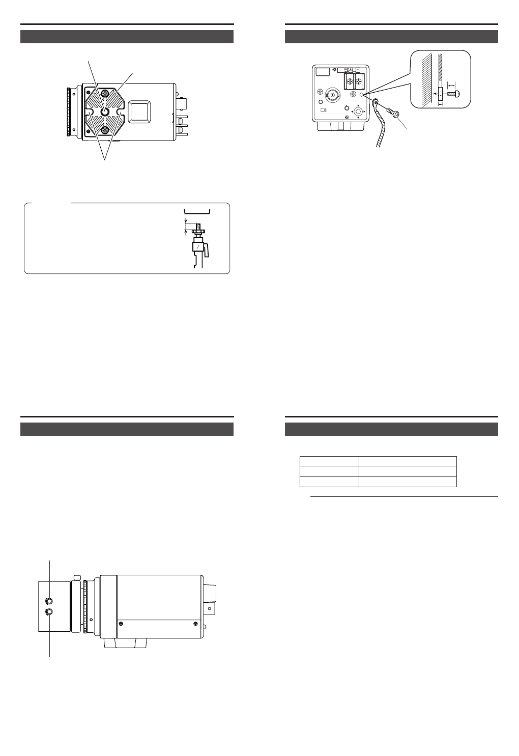
MAX.
7
mm
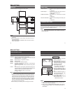
CONNECTION/INSTALLATION
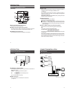
Camera mounting
screw hole
Camera mounting
bracket
Rotation prevention hole
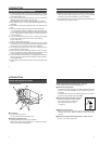
Mounting the camera
When mounting the camera on a fixer, pan/tilt, etc., use the camera
mounting screw hole located on the camera-mounting bracket.
CAUTION:
Use the screw with a length shorter than
7mm from a camera-mounting face.
Furthermore, make use of the rotation prevention hole to prevent the
camera from falling and securely mount the camera.
Special precautions must be taken for mounting the camera on a wall
or a ceiling. We are not liable for any damage caused by improper
installation.
19
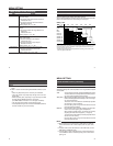
SEE INST-
RUCTION
MANUAL
DC12V
AC24V
1
2
CLASS 2 ONLY (U TYPE)
ISOLATED POWER ONLY
(E TYPE)
POWER
VIDEO OUT
INT
LL
SET
2mm
6mm
M3 × 6
SELECTOR
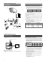
Fall Prevention
•Exercise maximum caution when installing the unit to the wall or
ceiling. You should not engage in the installation work yourself. Ask
a professional to do the job, since the fall of the unit can result in
injuries and accidents.
•When installing the unit on a fixer, Pan/Tilt unit, etc., make sure to
install it firmly using a rotation-preventing hole provided to prevent
fall.
•To prevent fall, connect the unit to a section with sufficient strength
(ceiling slab or channel) using a fall prevention wire such as a wire
chain and the like. Use the black screw on the back of the unit for
installation.
For the used safety cable, pay particular caution to the length,
strength, pull, material (insulation), etc.
•Specified screw (M3 × 6 mm)
Never use any screw longer than the specified length as the inside
can be damaged.
20
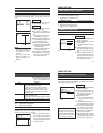
CONNECTION/INSTALLATION
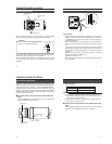
Auto iris lens adjustment
Connect the camera according to the connection method, turn it on,
display an image on the monitor, and check the image. The white bal-
ance adjustment mode is selected. ੬ Page 33 “WHITE BALANCE”
The camera has been factory-adjusted to the best position, but it may
need to be adjusted according to the object conditions or combination
of lenses. If the image is unnatural, adjust it as follows: (Also read the
instruction manual of the lens.)
Ⅵ For video auto iris lens (auto iris lens with built-in EE
amp)
Set the VIDEO/DC switch on the side of the unit to “VIDEO” and
adjust the LEVEL volume on the lens.
COLOR VIDEO CAMERA
ALC
LEVEL
Av Pk
L H
Level adjustment
ALC adjustment
(Does not operate)
21
• LEVEL adjustment
Monitor screen LEVEL turning direction
Too bright Counterclockwise (Toward L)
Too dark Clockwise (Toward H)
Memo
● If the sensitivity adjustment LEVEL is turned excessively to L,
the sensitivity increases because of the AGC function of the
camera, and the image looks grainy.
● At Low light levels, video iris lens may “Hunt”. Please adjust iris
level on lens to minimise hunting.
Ⅵ For DC auto iris lens (auto iris lens without built-in EE
amp)
Set the VIDEO/DC switch on the side of the unit to “DC” and adjust
the LEVEL in the LENS ADJUST screen. (੬ Page 35)