


9
Setup
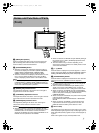
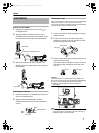
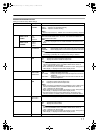
Mounting on KA-HD250U
1 Rotate the lock level as shown by the arrow ( ) in
the diagram below.
2 Align the bracket for viewfinder mount on top of
KA-HD250U with the groove at the viewfinder mount
base and insert from the back of the camera head
3 Rotate the viewfinder lock lever as shown in the
direction of the arrow ( ) and secure the viewfinder
to KA-HD250U.
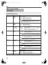
Removing the viewfinder
1 Rotate the lock lever in an anticlockwise direction as
shown in the diagram below.
2
While pressing the Release button, slide the
viewfinder toward the back of the camera head and
remove.
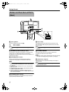
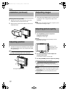
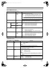
Connecting VF cable
When connecting the VF cable, be sure to turn off the POWER
switch on the camera or on the remote control unit first.
Connect the viewfinder [VF CABLE] terminal to the KA-HD250U
VF output terminal with the provided VF cable.
1 Insert the provided VF cable completely into the [VF
CABLE] terminal.
2 Loosen the set screw on the cable holder, tilt the
holder at an angle and insert the VF cable from the
bottom into the groove on the holder.
3 Press the cable holder squarely against the main unit
and secure the set screw.
If the cable holder is slanted, the set screw cannot be
secured and it may damage the screw hole of the
main unit.
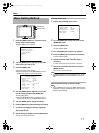
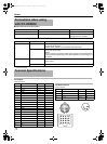
Caution:
To reduce emission of unwanted radio waves, install a core
filter on the VF cable connecting GY-HD250U and KA-HD250U.
● Use the core filter (black) provided with GY-HD250U.
● Install the core filter (black) as close as possible to
KA-HD250U.
Note:
● Use KA-HD250U with identification letter from (A) onwards
on the name plate for connecting to this unit. If there is no
identification letter, consult JVC dealer.
Installation
Mount Base
Bracket for viewfinder mount
Lock Lever
Lock Lever
Push
Release button
Lock Lever
VF Cable
Cable holder
Set screw
VF Cable
(Good)
(No good)
Core filter (black)
VF-HP840U_EN.book Page 9 Thursday, January 17, 2008 2:48 PM