


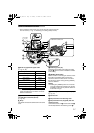
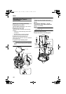
11
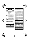
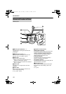
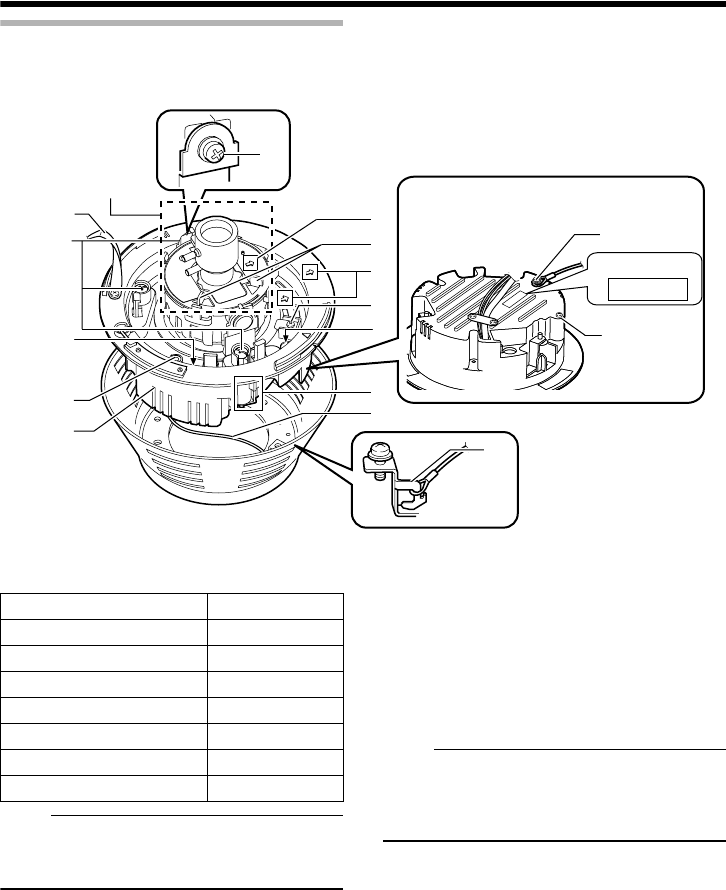
Camera unit/Inside the camera
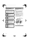
T This is when the dome cover, inner cover and outer case is removed.
How to remove ( A Pg. 17 eMounting on a ceilingf Steps 3. to 5.)
H Power supply/Alarm signal cable
(A Pg. 24, 26)
Note:
● Do not use PoE together with DC 12 V power
supply. Simultaneous connection will cause
failure or malfunction.
I [10BASE-T/100BASE-TX(PoE)] Connector
for LAN cable connection (RJ-45)
(A Pg. 26)
J Strap
This sheet connects the camera unit to the dome
cover.
K Fastening screw (x3)
This is the screw head of the ceiling mounting
bracket Q, which is used to embed the camera
in the ceiling.
L [RESET] Reset button
This is a button for rebooting the camera. Press
this button and release within 5 seconds to
reboot the camera. It takes about 1 minute for
the camera to reboot. During startup, [RESET]
button is disabled.
Note:
● Pressing the [RESET] button for 5 seconds
or longer switches the camera to the service
verification mode. Do not press the button for
5 seconds or longer.
M [MONITOR] Monitor terminal (RCA pin)
(A Pg. 27)
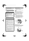
N Camera unit
O Fall-prevention wire fastening hook
P Fall-prevention wire (supplied) and wire
mounting screw
Connect the camera unit
N
and the outer case
C
with the fall-prevention wire fastening screw
O
.
MAC address
P
O
X
Q
K
N
M
R
S
T
U
V
P
W
J
Y
L
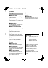
Behind the camera unit
Lens section
(A Pg. 13)
Signal name Cable color
Alarm input 1 Pink
Alarm input 2 Blue
Alarm output 1 Orange
Alarm output 2 Yellow
GND Brown
DC 12 V power supply+ Red
DC 12 V power supply- Black
VN-C215_EN.book Page 11 Monday, November 27, 2006 9:52 AM