21
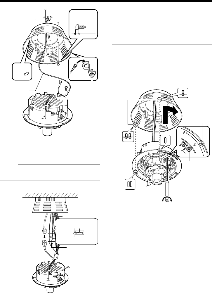
4.Connect the LAN cable. (A Pg. 26)
5.Connect the power cable and the alarm
cable. (A Pg. 24)
Memo:
● The power cable must not be connected
when PoE is used.
6.Wind the waterproof tape. (A Pg. 26)
Ⅵ Mounting
1.Align the secured outer case with the
position alignment mark of the camera.
Note:
● Make sure that the cables are not caught in
the outer case.
2.Turn the camera in the clockwise
direction.
T Check that the ○ mark can be seen. (Refer
to the diagram below)
3.Tighten the Camera Fastening Screws
and secure the camera.
Ⅵ Image adjustment
When the camera is mounted, adjust the image
settings while looking at the actual image.
(A Pg.27 eImage adjustmentf)
Ⅵ Mounting the Dome Cover
After the image adjustment is completed, mount
the dome cover.
Installation is complete when the dome cover is
mounted.
(A Pg.29 eMounting the Dome Coverf)
F
RONT
UP
3
2
1
Towards
fastening
hook
From the
ceiling slab
Towards the shooting
direction
T Loosen
sufficiently
Fall-prevention
wire
(not supplied)
Outer case
mounting screw
Less than 3 mm
4
5
6
Solder or crimp
Insulation tape
Wind the waterproof
tape.
3
2
1
Position
alignment
mark
Camera
Fastening
Screw
T Check
VN-C215_EN.book Page 21 Monday, November 27, 2006 9:52 AM


