


17
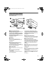
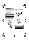
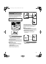
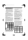
Connect the alarm input/output terminals with
external devices, such as a sensor or buzzer.
Plug/Unplug the cable while pressing the button
as shown in the diagram below.
Caution:
● Noises from an external source may cause
the camera to malfunction even when the
cable used is within 50 m. In this case, move
the cable away from the noise source.
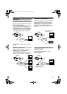
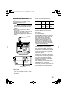
Alarm Input Terminal
Connect this terminal to sensor devices, such as
an infrared sensor, door sensor, metal sensor or
manual switch.
Ⅵ Input requirements
● No-voltage relay NPN open collector input
● Polarity of input detection can be selected
using a software
● Make/Break (500 ms and above)
● Circuit current at low level: 1 mA
● Applied voltage at high level: 3.3 V
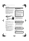
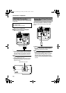
Alarm Output Terminal
Connect this terminal to annunciating devices,
such as annunciators, indicators, lights, or
buzzers.
Ⅵ Output requirements
● Equivalent to NPN open collector output (Set
the output logic using the Internet Explorer)
● Allowable applied voltage: DC12 V and below
● Allowable inflow current: 50 mA
●
Momentary (100 ms - 5000 ms) output
(Set time using the Internet Explorer
(A Page 46))
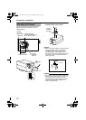
Caution:
● Connect the G terminal of this camera to the
GND terminal of the annunciating device or
alarm input sensor.
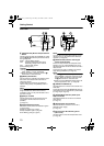
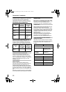
Alarm Input/Output Terminal
Connection
Cable to use
● Shielded cable
● Length of 50 m or shorter
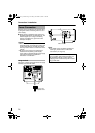
CAUTION
:NEVERUSE
PoE
AND
AC24V
ATTHE SAMETIME
DONOTCONNECT TOTHETELEPHONE NETWORK
SEEINSTRUCTIONMANUAL
CLASS2ONLYFORUSA
ISOLATEDPOWERONLY
FOREUROPEANDOTHER
MONITOR
OUT
10BASE-T/
100BASE-TX
PUSH
OUTPUT
ALARM
INPUT
2
AC24V
1
PoE
G 2121
Push
DC3.3 V
R
3.3 V
1mA
VCC
OUT
GND
GND
OUT
R
(Alarm Input Equivalent Circuit)
G Terminal
INPUT 1 or
2 Terminal
VN-V25U
Sensor Example
(1)
Sensor Example
(2)
Relay Switch, etc.
IN
R
DC 12 V
GND
Annunciating
Device Example
VN-V25U
G Terminal
OUTPUT 1
or 2 Terminal
(Alarm Output Equivalent Circuit)
VN-V25U_EN.book Page 17 Friday, November 2, 2007 11:26 PM