


11
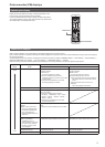
Setting menu items
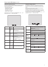
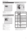
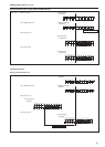
TOP MENU
This is the first screen displayed when you hold down the MENU button
Select one of the menus
TOP MENU
OPERATION
MAINTENANCE
OPERATION
Select this to open the OPERATION menu screen
MAINTENANCE
Select this to open the MAINTENANCE menu screen
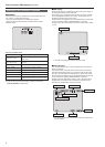
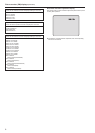
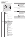
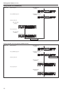
OPERATION menu
This is the selection screen for the OPERATION menu
Moving the cursor to the “OPERATION” menu title and then pressing the
SELECT dial redisplays “TOP MENU”
OPERATION
SETTING1
SETTING2
HD/SD PHASE
BAR ID
INCOM/MIC
SETTING1
Select this to display the SETTING1 screen
SETTING2
Select this to display the SETTING2 screen
HD/SD PHASE
Select this to display the HD/SD PHASE screen
BAR ID
Select this to display the BAR ID screen
INCOM/MIC
Select this to display the INCOM/MIC screen
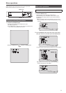
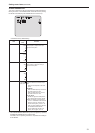
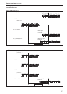
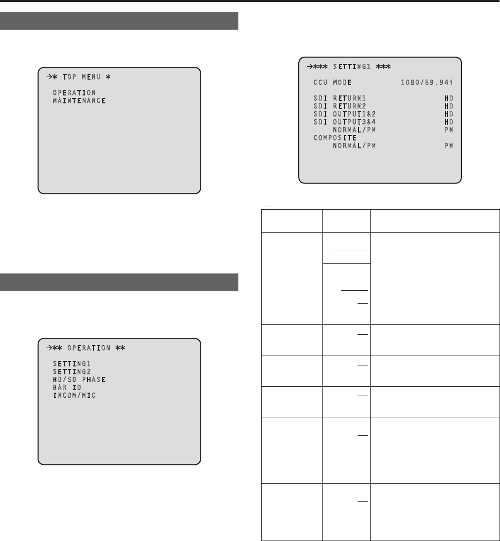
SETTING1 Screen
This is the selection screen for the SETTING1 menu
Moving the cursor to the “SETTING1” menu title and then pressing the
SELECT dial redisplays the OPERATION menu one level up
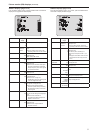
SETTING1
CCU MODE 1080/59.94i
SDI RETURN1 HD
SDI RETURN2 HD
SDI OUTPUT1&2 HD
SDI OUTPUT3&4 HD
NORMAL/PM PM
COMPOSITE
NORMAL/PM PM
indicates the factory default setting
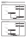
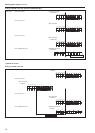
Item
Setting
value
Remarks
CCU MODE
5994 Hz:
1080/5994i
1080/50i
Set the format of the signal to be output
from the unit
50 Hz:
1080/5994i
1080/50i
SDI RETURN1
HD
SD
Set the format of the return signal to be
input to [HD/SD SDI 1] of the RETURN
IN connectors
SDI RETURN2
HD
SD
Set the format of the return signal to be
input to [HD/SD SDI 2] of the RETURN
IN connectors
SDI OUTPUT1&2
HD
SD
Set the format of the signals to be
output from [1] and [2] of the HD/SD
SDI OUT connectors
SDI OUTPUT3&4
HD
SD
Set the format of the signals to be
output from [3/PM] and [4/PM] of the
HD/SD SDI OUT connectors
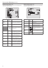
SDI OUTPUT3&4
NORMAL/PM
NORMAL
PM
Set the signal to be output from [3/PM]
and [4/PM] of the HD/SD SDI OUT
connectors
NORMAL:
Output the main line images
PM:
Output the picture monitor images
COMPOSITE
NORMAL/PM
NORMAL
PM
Set the signal to be output from
[OUT/PM] of the VBS connectors
NORMAL:
Output the main line images
PM:
Output the picture monitor images
When the SDI OUTPUT3&4 NORMAL/PM item and COMPOSITE
NORMAL/PM item are set to “NORMAL”, the menus and statuses will
not be able to be displayed because the picture monitor images will
not be output
When one of items is set to “NORMAL”, the other one is set to “PM”
as both of the items cannot be set to “NORMAL”