11
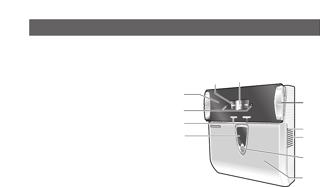
MAJOR OPERATING CONTROLS AND THEIR FUNCTIONS
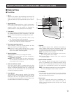
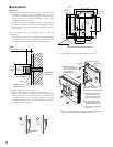
q Mirror
This mirror is used for eye positioning at the time of iris
data enrollment/recognition. View the mirror from the
front side where you can position both eyes in the mir-
ror.
w Guide indicator
When a user comes within 50 cm {1.64 ft.} of the front of
an iris camera, this indicator will appear in the mirror for
guidance. Adjust your eye position by following the
guide indicator or voice guidance from the speaker.
e Front panel
Eye image capturing cameras and a near-infrared light
are located behind this panel. Depending on the user,
the near-infrared light (blinking red light) can be seen.
Notes:
• Avoid covering the front panel with a hand or cloth,
etc. That may cause invalid recognition.
• Avoid pinching objects between the front panel and
the main unit. That may cause a malfunction.
r Eye image capturing cameras
These cameras, which are located behind the front
panel, are used for eye image capturing.
Note: Avoid covering these cameras with a hand or
cloth, etc. Or avoid placing smudges on these cam-
eras. It may cause invalid recognition.
t Result indicators
These indicators inform you of recognition results.
ACCEPT: This indicator lights up when recognition is
successfully completed.
REJECT: This indicator lights up when recognition is
not successfully completed or the user's iris data is
not enrolled in the iris camera.
y Video surveillance camera
This colour camera, which is located behind the front
cover, is used for facial monitoring. If you connect this
camera to external equipment such as a digital disk
recorder, you can record user's face and surroundings
to check the capturing condition.
u Live indicator
This indicator is blinking during standby. The blinking
speeds up when a user stands where he/she can see
both eyes in the mirror and guidance starts. The indica-
tor can be set to be continuously on or off. Refer to sys-
tem administrators for details on the settings.
i Speaker
This speaker outputs voice guidance that guides a
user’s position and gives the recognition result. The
voice guidance can be set to any of the following. Refer
to system administrators for details on the settings.
Mute: Voice guidance is not output.
Simple: Shutter sound and recognition result are out-
put. Voice guidance is not output.
Full: Voice guidance, shutter sound, and recognition
result are output.
o Audio volume controller
This controller adjusts the audio level of voice guid-
ance. For adjustment, use a Phillips screwdriver that is
3 mm {0.12 in.} in diameter and more than 25 mm {0.98
in.} long. It is recommended to use a non-conductive
driver.
Note: Avoid adding excessive force to the screwdriver.
That may damage the audio volume controller.
!0 Tilt handles
You can adjust the angle of the front panel by holding
these handles. Adjust the handles so as to position both
eyes at the centre of the mirror.
!1 Front cover
This cover is removed at the time of installation, con-
nection or maintenance. Users should not open it.
(Refer to service personnel when the front cover needs
to be opened.)
REJECT ACCEPT
B
M
-
E
T
3
0
0
A
u
!0
o
i
t
r
y
e
q
w
!1
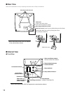
■ External View
● Front View


