18
19
20
Pin No.
16
17
Port NamePin No.
1
2
3
4
14
Port Name
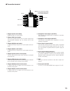
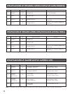
SPECIFICATIONS OF WIEGAND CONNECTORS (FOR CARD READER)
POWER
GND
DATA 0
DATA 1
OUT
–
IN
IN
Wiegand 5 V
Wiegand GND
Wiegand DATA 0
Wiegand DATA 1
5 V, 100 mA (Max)
0 V
0 V to 5 V, 24 mA (Max), Wiegand I/F
Active low
0 V to 5 V, 24 mA (Max), Wiegand I/F
Active low
I/O Signal Description Remarks
Port Name
POWER
GND
DATA 0
DATA 1
Note: This port is for wiring designation convenience only.
IN*
–
OUT
OUT
Wiegand 5 V
Wiegand GND
Wiegand DATA 0
Wiegand DATA 1
5 V
0 V
0 V to 5 V, 24 mA (Max), Wiegand I/F
Active low
0 V to 5 V, 24 mA (Max), Wiegand I/F
Active low
I/O Signal Description Remarks
OUTPUT
ACCEPT
OUTPUT
REJECT
OUTPUT
POWER
DETECTION
OUTPUT
TAMPER
DETECTION
GND
OUT
OUT
OUT
OUT
–
Recognition result output 1
(recognition ACCEPT)
Recognition result output 2
(recognition REJECT)
Alarm output 1
(power status)
Alarm output 2
(tamper detection)
Alarm output
(COMMON)
Open collector output
Normally Open contact
Open collector output
Normally Open contact
Open collector output
Normally Closed contact
Open collector output
Normally Open contact
0 V for ALARM OUTPUT
I/O Signal Description Remarks
SPECIFICATIONS OF WIEGAND CONNECTORS (FOR ACCESS CONTROL PANEL)
SPECIFICATIONS OF ALARM OUTPUT CONNECTORS
Pin No.
6
7
8
9
Note: The Wiegand communication settings are made with the administration software. Refer to system administrators.


