19
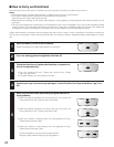
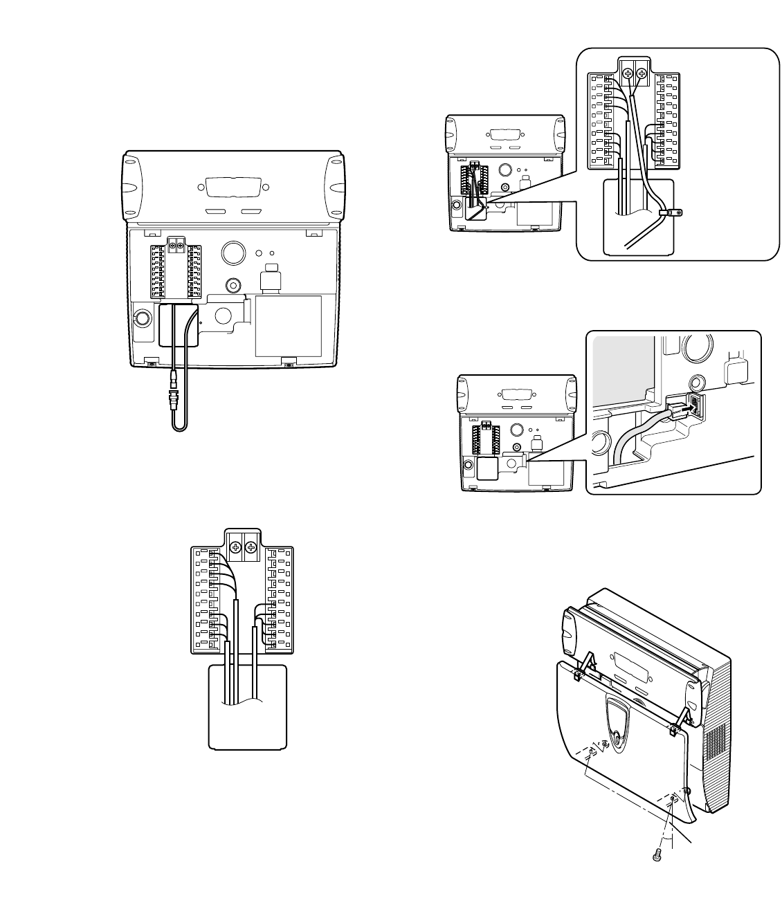
7. Attach the LAN cable to the LAN connector.
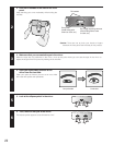
8. After installation, attach the front cover to the iris cam-
era by fixing the supplied tamper proof screws with the
supplied screwdriver tool.
Notes:
• Take care not to lose the supplied tamperproof screw-
driver tool, as it is required at the time of relocation and
setting.
• The front panel is covered with the protection film for
preventing damage. Be sure to detach the film after the
installation process of the iris camera.
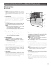
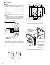
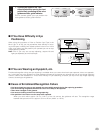
Tam perproof screws x 2
Approx. 15 °
The tamperproof screw holes are
inclined to the front side approx. 15 °
as you can easily fasten the screws
while the iris camera is mounted to the wall.
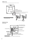
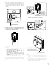
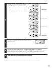
3. When you use the built-in video surveillance camera,
connect the video cable of the video surveillance cam-
era to the BNC connector of the video input cable con-
nected to an external device (for example, a digital disk
recorder).
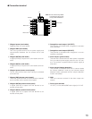
4. Connect the cables to the Wiegand and alarm output
connectors as shown in the illustration. (Refer to p. 13
for details on each cable connection.)
5. Connect the power cable to the iris camera.
Cautions:
• Pass the cables through the cable hole and lead
them out of the rear or bottom side.
• If the cables are lead out of the bottom side, coat
the cables with cable covers, etc.
•When using 12 V DC power cable, do not mistake +
and –. The wrong cable connection may cause
problems.
•Use an external power-supply device that complies
with the safety standards. (Refer to p. 33.)
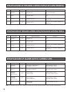
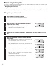
6. Fix the power cable to the iris camera with the supplied
clamping tool and clamping screw to avoid disconnec-
tion.
Cables
Fix the power
cable to the iris
camera with the
supplied
clamping tool and
clamping screw.
Video cable
Coaxial cable
from a connected device


