


14 Pelco Manual C1902M (11/96)
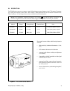
5.0 CAMERA INSTALLATION
ATTENTION: Installation should be per-
formed by qualified service personnel only, in
accordance with the National Electrical Code
or equivalent/applicable local codes.
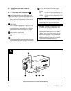
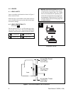
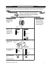
When attaching the camera to a ceiling bracket or tri-
pod, attach the supplied mounting bracket. The bracket
may be attached to either the top or bottom of the cam-
era. Use the supplied 1/4" UNC-20 screw to attach the
camera to the tripod or ceiling bracket.
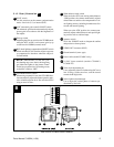
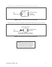
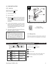
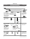
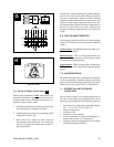
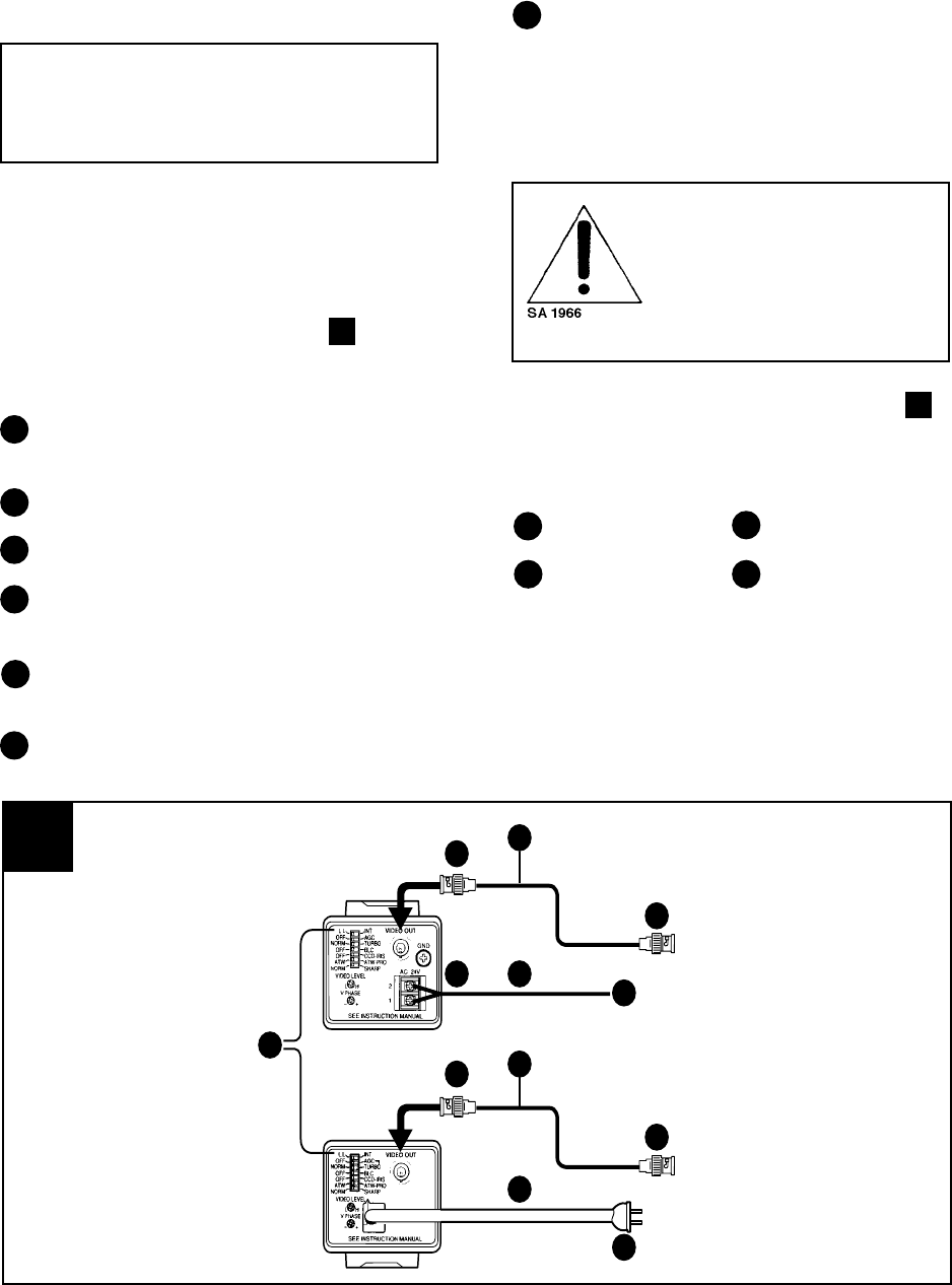
5.1 Connections (Illustration F )
Using an internal synchronization signal.
Set the L.L/INT switch to “INT” (internal synchro-
nization).
Connect with VIDEO OUT connector.
75-ohm coaxial cable
Connect with VIDEO IN connector on a video
monitor, etc.
To power supply (CC4600-2, CC4600-2X); to a
wall outlet (CC4600-3)
Power cord
4
1
3
7
F
3
4
2
1
7 6
5
4
3
2
6
5
CC4600-2 & -2X
CC4600-3
2
5
Connecting the CC4600 Series Cameras
1
2
3
4
To AC 24V terminals 1 and 2 (CC4600-2,
CC4600-2X)
When using an external (L.L) synchronization signal,
set the L.L/INT switch (1) to L.L and make connec-
tions as above.
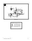
CAUTION: Be sure cable wires
are routed so as to not pinch or rub
when connected to pan/tilt units.
Frayed, pinched or broken wires
can cause fire/shock hazards or
system failure.
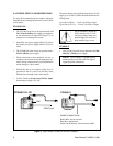
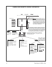
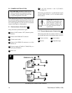
5.2 Phase Adjustment (Illustration G )
When using more than one camera, connect to a cam-
era switcher and set the vertical phase range as follows:
Camera switcher Vertical phase
Monitor Adjustable range
6