


Chapter 1 Overview
Chapter 1 Overview 23
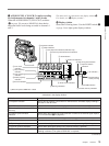
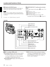
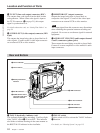
9 LENS connector (12-pin)
If you use a lens with cable, connect the lens cable.
0 VIDEO OUT connector (BNC)
This outputs the video signal captured by the
camcorder.
!¡ REMOTE connector 2 (10-pin)
Connect the optional RM-M7G Remote Control Unit
to this connector. Set the CAMERA HEAD SELECT
switch on the bottom of RM-M7G to 1.
You can also connect a remote control unit with
microphone.
Note
EZ mode cannot be used if the RM-M7G is connected
to the camcorder.
For more information about a remote control unit with
microphone, contact your Sony dealer.
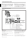
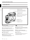
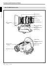
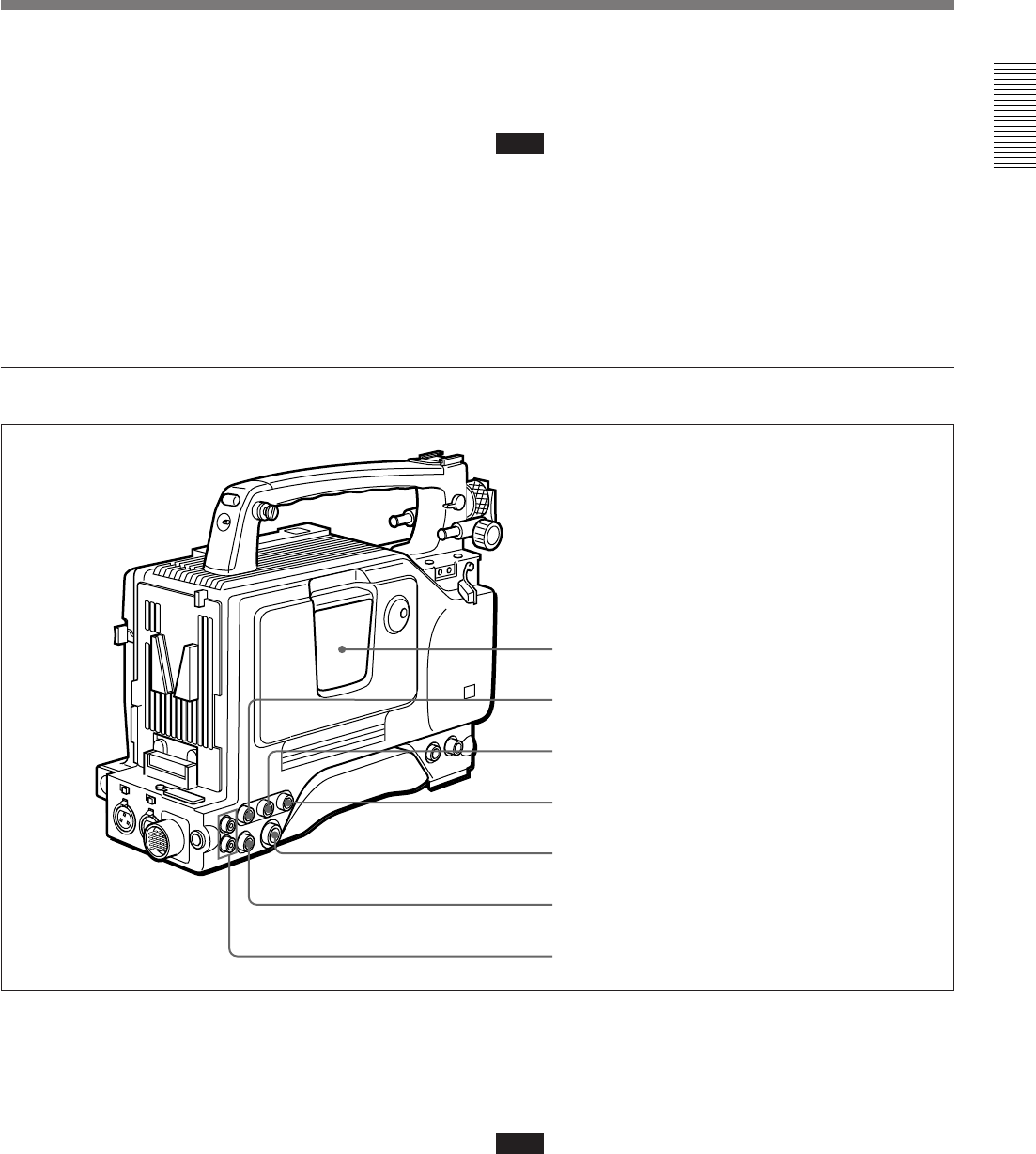
Rear section
1 Cassette holder
Power the camcorder and press the EJECT button to
open the lid. Insert the cassette and close the lid by
pressing the indication “PUSH” .
2 GEN LOCK IN (gen lock video input) connector
(BNC)
When synchronizing the camcorder to an external
signal, input a reference video signal (VBS or BS).
1 Cassette holder
2 GEN LOCK IN connector
3 TC IN connector
4 TC OUT connector
5 S VIDEO OUT connector
6 MONITOR OUT connector
7 AUDIO OUT CH-1/CH-2 connectors
3 TC IN (time code input) connector (BNC)
Input an external signal for synchronizing the built-in
time code generator. Use an SMPTE (DSR-300) or
EBU (DSR-300P) time code signal.
Note
Use a jitterless LTC signal. Using an LTC signal
reproduced by other equipment may cause the
camcorder to malfunction.