


74 Chapter 4 Viewfinder Screen Indications and Menus
Chapter 4 Viewfinder Screen Indications and Menus
TCG 12:34:56:00 PARA
NG AUTO BLACK
-OK-
198
EZ FOCUS
:LOW LIGHT 98 04 01
SS : 1/1000 10:00AM
30-25 DIAG ERROR
REC
TAPE NEAR END REC2
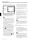
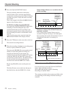
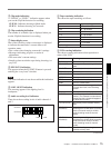
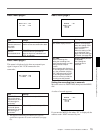
During normal operation, the following items can be
indicated in the viewfinder.
1 VCR operation status indication
!™ VCR warning indication
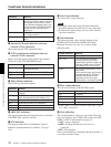
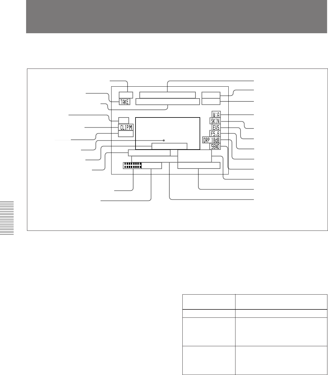
DISPLAY switch
setting
Time data displayed
COUNTER CNT: Tape transport time
TC TCG: a time code from the time code
generator
TCR: a time code from the time code
reader
U-BIT UBG: a user bit value from the time
code generator
UBR: a user bit value from the time
code reader
2 TAKE/CUE indication
3 Recording time or time data
indication
a)
4 NG indication
5 Clip mode indication
6 Clip remaining
indication
7 Status display area
8 EZ FOCUS indication
9 LOW LIGHT indication
a)
!º Audio recording level indicators
a)
!¡ Tape remaining indication
a)
!£ External VCR status
indication
c)
!¢ VCR recording mode
indication
c)
!∞ White balance indication
!§ SKIN DTL indication
!¶ EVS indication
!• Lens f-stop indication
a)
!ª Gain indication
a)
@º Filter setting indication
a)
@¡ Clock indication
a), b)
@™ Voltage/error indication
@£ Shutter setting indication
a)
a) Whether or not to display can be selected by menu setting.
b) This is recorded over the picture being shot.
c) Displayed only when an external VCR is connected
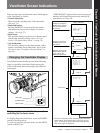
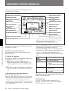
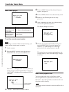
Viewfinder Normal Indications
The significance of each of the indications shown in
the figure is as follows.
1 VCR operation status indication
This indicates the VCR’s current operation status
(REC, PLAY, etc.).
2 TAKE/CUE indication
This displays a TAKE or CUE indication when using
the ClipLink function for recording.
TAKE: When recording in Mark mode, this
indication appears when a Mark IN point is set
and disappears when the next Mark OUT point is
set.
CUE: When recording in Cue mode, this indication
appears for about 1 second when a Cue point is
set.
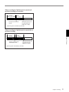
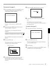
3 Recording time or time data indication
This shows the following values.
• When the REC TIME switch is in the TTL position:
The total recording time (When an external VCR is
connected, you can select whether to show the
recording time of the internal VCR or of the external
VCR using advanced menu page 4. See page 86 for
more information.)
• When the REC TIME switch is in the DUR position:
The duration of the current recording cut
• When the REC TIME switch is in the OFF position
and the item TC IND in advanced menu page 6 is set
to “ON”: A time data value depending on the
DISPLAY switch settings as shown in the following
table
Time data values appear during playback, fast forward,
rewind, or recording review.
4 NG indication
An “NG” (No Good) indication appears if you
designate a recorded scene as “NG” when using the
ClipLink function for recording.