14
Functions
DFW-SX910/X710
PAINT
This feature enables you to shift the reference point of
the White Balance. If you change the parameter of this
feature, the white-balance adjustment references to a
color other than white.
User Memory Area
The camera is equipped with 256 bytes of nonvolatile
memory to hold information you need.
The information is read or written by quadlet. Both
Quadlet Read/Write and Block Read/Write
transactions are available. The information will be
preserved even if the power to the camera is turned off.
Non-IIDC Features
The following features are not defined by the IIDC
standard.
1394 Bus Synchronization
Cameras connected to the same bus are automatically
synchronized. Specifically, the start of exposure will
be the same for all cameras running at the same frame
rate.
The DFW-SX910/X710 series and XCD-SX910/X710
series cameras uses the same automatic bus
synchronization system. The 1394 bus is a shared
resource with finite bandwidth. The number of
cameras that can be simultaneously is limited by the
ISO bandwidth available (~32 MBytes/sec) and ISO
channels (4-8 depending on your computer 1394
interface). Bandwidth is allocated based on the
resolution and frame rate selected for the camera. To
reduce the bandwidth for a camera, reduce the output
image size and/or the frame rate.
For instance, if a camera is to transmit 1280×960 in
YUV4:2:2 at 7.5 fps, approximately 18.4 MBytes/sec;
more than half the available bandwidth. Reducing the
frame rate to 3.75 fps reduces the bandwidth to
approximately 9.2 MBytes/sec allowing 3 cameras to
transmit simultaneously.
CPU operation timing can cause jitter in the 1394 bus
synchronization of approximately 4 microseconds.
External hardware (trigger) synchronization can be
used to ensure further accuracy. To synchronize
cameras on different 1394 busses, use a common
hardware trigger to all the cameras.
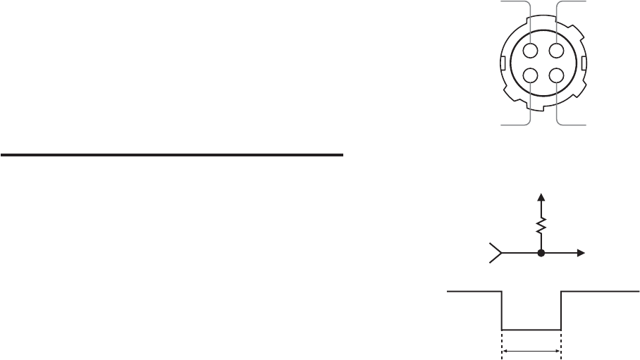
Exposure Out
A signal that indicates an exposure time is output from
pin 1 on the 4-pin connector on the rear panel.
When the hardware trigger feature is used, the signal
above is not output. The output is the open-corrector
type.
1
2
4
3
The LOW period that is given by an output wave form
is an approximate guideline. It does not correspond
exactly to the actual exposure time.
+5 V
1 kΩ
Exposure
time
NC Exposure out
GND
Trigger input


