


15
Control
DFW-SX910/X710
Camera Command
Status Register
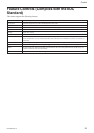
This camera complies with the IIDC 1394-based
Digital Camera Specification, version 1.30 (hereinafter
referred to as IIDC v1.30).
The standards document can be purchased from
1394TA (the 1394 Trade Association). Because it is
very helpful in understanding the explanations in this
Technical Manual, we recommend that you purchase a
copy of IIDC v1.30.
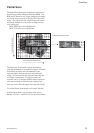
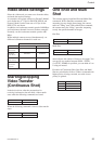
Memory Map
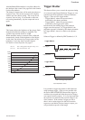
1394 devices have a 64-bit address space. The upper
10 bits show the bus ID (0~1023), and the next six bits
show the node ID (0~63). The IIDC standard requires
the next 20 bits to be 1.
The remaining 28 bits can be allocated to the camera
as addresses, but in reality, the first 4 bits are fixed at
0, so the largest number of bits that can be allocated to
the camera as address space is 24 bits.
The bus and node IDs may be changed if the topology
is restructured because of bus reset, so only the least
significant 32 address bits are shown in this Technical
Manual.
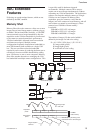
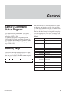
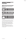
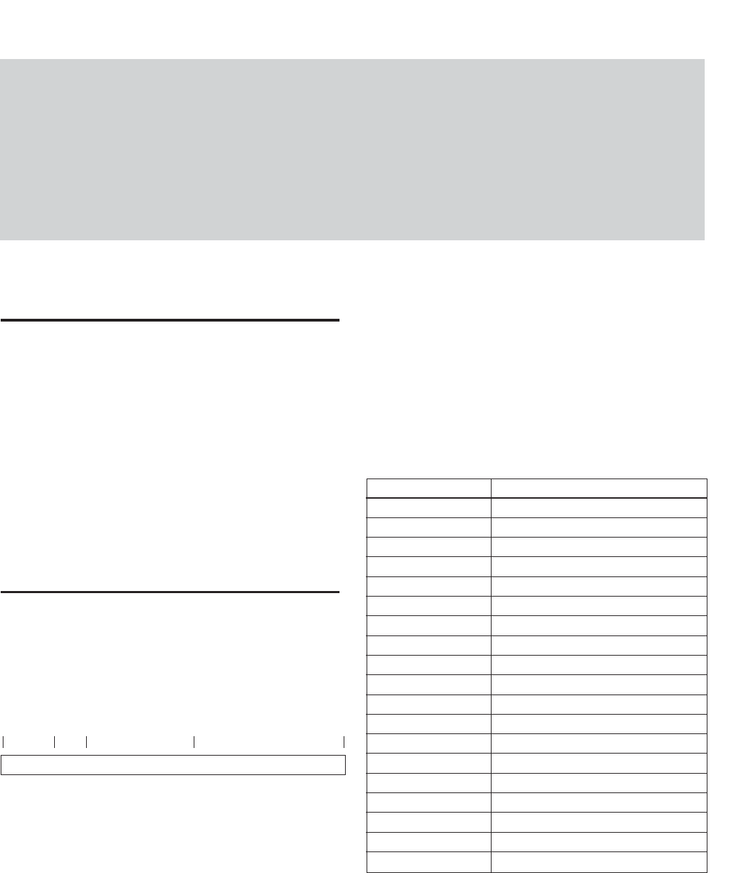
Address Register
F0000000 Base address
F0000400 ConfigROM area
F0F00000 Base addresses for camera commands
F0F00000 CameraInitialize
F0F00100 Video Format Inq
F0F00180 Video Mode Inq
F0F00200 Frame Rate Inq
F0F002E0 Format7 CSR Inq
F0F00400 Basic Func Inq
F0F00500 Feature Element Inq
F0F00600 Isochronous Control register
F0F0071C AbsoluteControlCSR Inq for Shutter
F0F00800 FeatureControl
F0F00970 AbsoluteControlCSR for Shutter
F0F10000 Format7Mode0 CSR
F0F30000 Access Control Register
F0F40000 Memory Shot control
F0F50000 User Memory
Control
---BusID--- --------Must be 1--------
----
Address used by the camera
----
NodeID
bbbbbbbb | bbnnnnnn | 11111111 | 11111111 | 11110000 | 11110000 | 00000000 | 00000000