


7
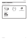
Overview
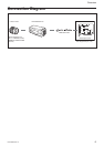
DFW-SX910/X710
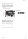
Location of Parts and Operation
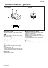
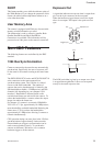
1 Lens mount (C-mount)
Attach any C-mount lens or other optical equipment.
Note
The lens must not project more than 7 mm (
9
/32 inch)
from the lens mount.
1 Lens mount face 2 7 mm (
9
/32 inch) or less
2 Flange back hole
Adjust the flange back by adjusting the screw at the
bottom of this hole.
3 Pilot lamp
This lamp indicates the camera module operation
states:
OFF: Camera power OFF
Green: Camera power ON/Video signal output OFF
Orange: Camera power ON/Video signal output ON
4 Tripod hole
Install a tripod into this hole.
Rear PanelFront/Top/Bottom
1
2
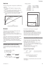
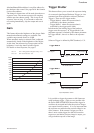
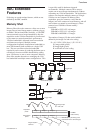
5 TRIG IN/Exposure OUT connector
Connect the trigger signal generator (trigger output
connector) to this connector.
When trigger is OFF, or software trigger is ON, a
signal that indicates the exposure time is output from
pin 1 of the camera.
For details on the exposure out, see “Exposure Out”
(page 14).
6 CAMERA connector
Connect the IEEE1394 camera cable (supplied) to this
connector.
1
3
4
5
6
2