


6
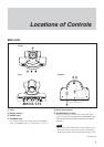
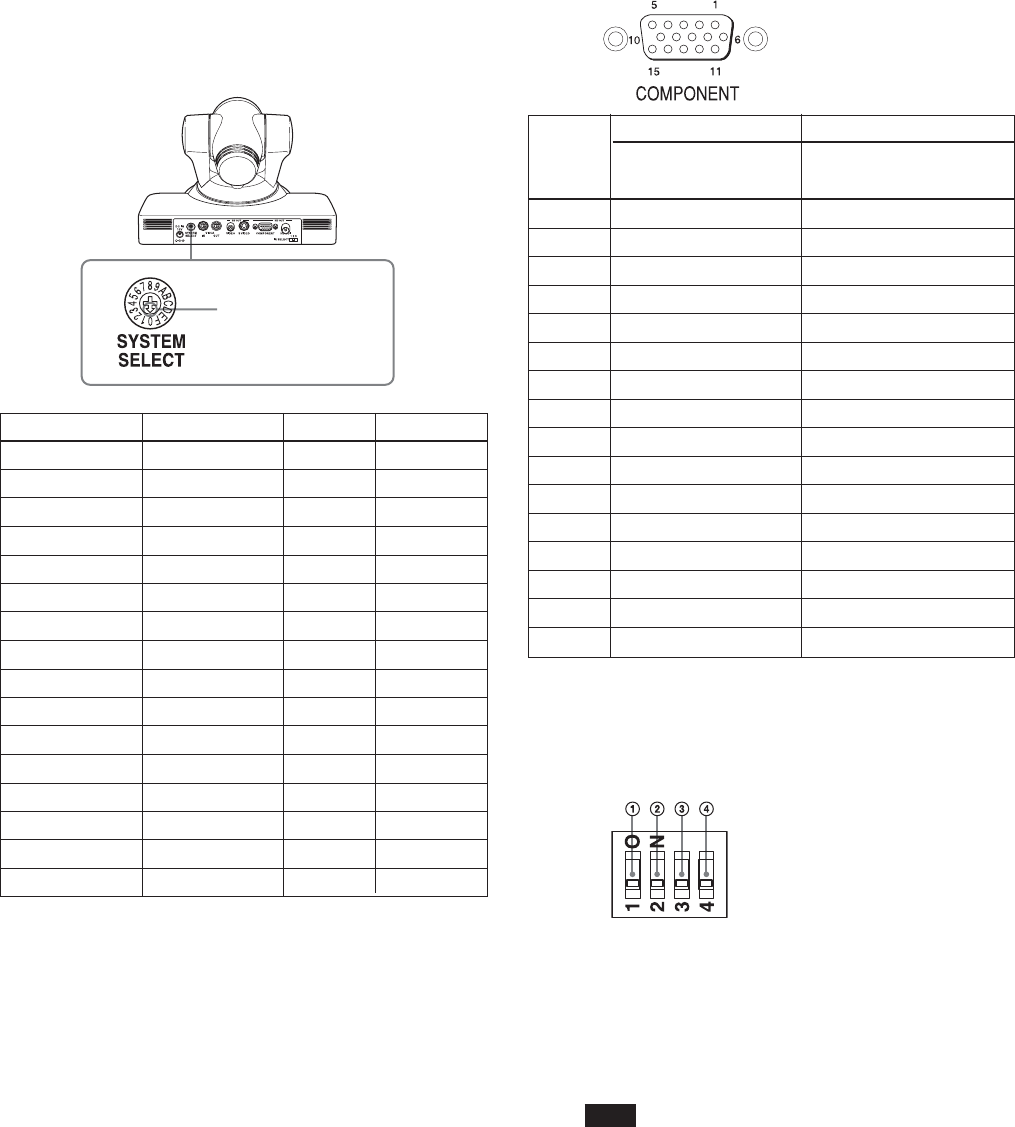
Locations of Controls
the power of the camera by connecting it to an AC outlet
using the supplied AC power adaptor and AC power
cord, or by using the VISCA command. When you set
this switch in the standby mode, press the POWER
switch of the remote commander. This switch setting
becomes effective.
• Be sure to use a Phillips-head screwdriver when
changing the switch position. If you use a tool other than
the designated screwdriver, the crossed groove may be
damaged.
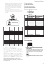
a: Outputs the image signal.
—: Does not output the image signal
LB: Abbreviation of LETTER BOX. A video signal
with the 16:9 aspect ratio is output by adding a blank
area (no signal, black) top and bottom to display the
image without distortion on a monitor that uses the 4:3
aspect ratio.
CR: Abbreviation of CROP. A video signal with the
4:3 aspect ratio is output, by cropping both the left and
right sides of a video image with a 16:9 aspect ratio.
SQ: Abbreviation of SQUEEZE: A video signal of the
image compressed horizontally is output so as to
display the image without distortion on a monitor with
a 16:9 aspect ratio.
7 VISCA IN connector
8 VISCA OUT connector
9 SD OUT VIDEO connector
0 SD OUT S VIDEO connector
qa HD OUT COMPONENT connector
qs HD OUT HD-SDI connector
qd IR SELECT switch
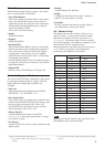
qf BOTTOM switches
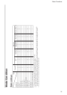
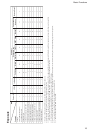
Switch position Video format HD OUT SD OUT
0 1080i/59.94 a —
1 1080p/29.97 a —
2 720p/59.94 a —
3 720p/29.97 a —
4 NTSC (LB) — a
5 NTSC (CR) — a
6 NTSC (SQ) — a
7 No output — —
8 1080i/50 a —
9 1080p/25 a —
A 720p/50 a —
B 720p/25 a —
C PAL (LB) — a
D PAL (CR) — a
E PAL (SQ) — a
F No output — —
Set this arrow to the
desired video format.
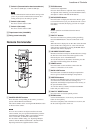
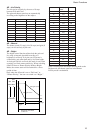
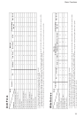
Pin No. Function
At YPbPr COMPONENT At YPbPr COMPONENT
setting (at SYNC) setting (at VD)
0 Pr-OUT Pr-OUT
1 Y-OUT Y-OUT
2 Pb-OUT Pb-OUT
3 GND GND
4 GND GND
5 GND GND
6 GND GND
7 GND GND
8 GND GND
9 No connection No connection
10 GND GND
11 GND GND
12 No connection No connection
13 HD-OUT HD-OUT
14 Tri-level SYNC-OUT Bi-level VD-OUT
15 No connection No connection
1 Switch 1 (infrared remote commander signal
output switch)
Set to ON to enable output of the infrared signals, that
are transmitted from the Remote Commander, from the
VISCA IN connector, or set it to OFF to disable the
output.
Note
Set IR ON/OFF before turning on the power. If you set
IR ON/OFF after turning on the power, the setting is
ignored.