


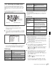


Chapter 7 Menu Displays and Detailed Settings
131
7-3 Adjustments and Settings From Menus
3
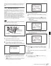
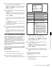
Turn the MENU knob to move the b mark to the item
you want to set, and press MENU knob.
The b mark on the left of the selected item changes to
a z mark and the z mark on the left of the setting
changes to a ? mark.
4
Turn the MENU knob to change the setting, and press
the MENU knob.
The z mark on the left of the selected item changes to
a b mark and the ? mark on the left of the setting
changes to a z mark.
Any of –3, 0, 3, 6, 9, 12, 18, 24, 30, 36, 42 or 48 dB
can be set for each of the L, M, and H positions, in any
sequence.
For TURBO, any of –3, 0, 3, 6, 9, 12, 18, 24, 30, 36,
42 or 48 dB can be selected.
To change the gain corresponding to another switch
position, return to step 3.
5
To end the menu operation, set the MENU ON/OFF
switch to OFF or close the cover of the menu operating
section.
The menu display disappears, and the current status of
the camcorder is shown along the top and bottom of
the screen.
7-3-2 Selecting the Output Signals
When the CBK-SD01 is installed, you can select the type
of video signals (VBS/SDI) from the VIDEO OUT
connector on the OUTPUT page of the USER menu.
Use the POWER SAVE page to specify whether or not to
enable DV stream output from the i.LINK DV IN/OUT
S400 connector of this unit.
When DV stream output is enabled, it is output when the
recording format is any of MPEG IMX 50Mbps, 40Mbps,
30Mbps or DVCAM.
To select the signal output from the VIDEO
OUT connector
Proceed as follows.
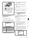
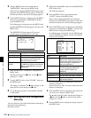
1
Set the MENU ON/OFF switch to ON.
The last accessed menu page appears on the screen.
2
Turn the MENU knob until the OUTPUT page
appears, then press the MENU knob to select the page.
3
Turn the MENU knob to move the b mark to “REAR
BNC OUT SEL”, and press the MENU knob.
The b mark on the left of “REAR BNC OUT SEL”
changes to a z mark and the z mark on the left of the
setting changes to a ? mark.
4
Turn the MENU knob to change the desired setting,
and press the MENU knob.
The z mark on the left of the selected item changes to
a b mark and the ? mark on the left of the setting
changes to a z mark.
5
To end the menu operation, set the MENU ON/OFF
switch to OFF or close the cover of the menu operating
section.
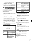
To enable DV stream output
Proceed as follows.
1
Holding down the MENU knob, move the MENU ON/
OFF switch to ON.
The TOP menu appears.
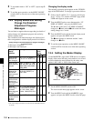
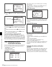
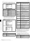
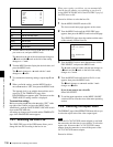
Item Description
LCD BRIGHT <L> Adjusts the LCD brightness when the
LCD switch is in the L position.
LCD BRIGHT <H> Adjusts the LCD brightness when the
LCD switch is in the H position.
LCD COLOR Adjusts the color saturation of the LCD.
i.LINK MODE Selects whether or not to use the
i.LINK connector SBP2 interface.
REAR BNC OUT
SEL
Selects the type of the video signal to
be output from the VIDEO OUT
connector.
SDI : Outputs the SDI signal. When
SDI is selected, connect the
VIDEO OUT connector to the SDI
IN connector of the video monitor.
VBS: Outputs the analog composite
video signal. When VBS is
selected, connector the VIDEO
OUT connector to the VIDEO IN
connector of the video monitor.
This setting allows you to save the
power.
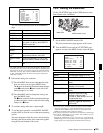
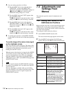
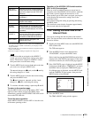
U01 OUTPUT
LCD BRIGHT <L> : 0
LCD BRIGHT <H> : 0
LCD COLOR : 0
i.LINK MODE : AV/C
PB WIDE ID(IMX) :: THROU
REAR BNC OUT SEL: VBS
LIVE LOGGING : OFF
TOP