


Parts Identifications
17
Overview
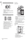
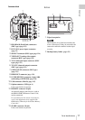
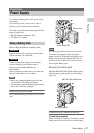
Connector block
1.HD SDI A/B (Dual-Link) connectors
(BNC type) (page 125)
2.DC IN (DC power input) connector
(page 22)
3.SDI OUT connector (BNC type) (page 124)
4.VIDEO OUT (analog video output)
connector (BNC type) (page 124)
5.TC IN (timecode input) connector (BNC
type) (page 131)
6.TC OUT (timecode output) connector
(BNC type) (page 132)
7.GENLOCK IN connector (BNC type)
(page 131)
8.HDMI OUT connector (page 124)
9.i.LINK (HDV/DV) connector (4-pin, S400
conforming to IEEE1394) (page 128)
10.USB connector (Mini B) (page 125)
11.Option connector (USB type A)
It does not function at present.
12.REMOTE connector (8-pin)
An external remote control device, such as
the RM-B150/B750 Remote Control Unit,
can be connected.
For operation from the remote control device,
refer to the Supplement in the supplied CD-
ROM labeled “Manuals for Solid-State Memory
Camcorder.”
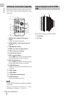
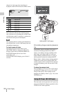
13.SPARE connector (10-pin)
It does not function at present.
Bottom
1.Tripod receptacles
Check that the size of the hole matches the
screw of the tripod. If they do not match, the
camcorder cannot be attached to the tripod
securely.
2.Backup battery holder (page 135)
MENU SEL/SET CANCEL
BATTERY
RELEASE
SDI OUT
VIDEO OUT
TC IN
TC OUT
GENLOCK IN
SLOT SELECT
ON OFF
PICTURE PROFILE
HD SDIAB
AB
DC IN
8
9
10
11
12
13
1
234567
Note
12