


Maintenance
4-6
DPO4000 Series Service M anual
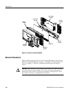
Overview of Removal Procedures
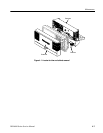
Refer to Figures 4--1 and 4--2 for the location of modules that you are removing
or installing. If you are disassembling the instrument for cleaning, refer to the
Inspection and Cleaning procedure on page 4--1 for instructions.
The Mechanical Parts List chapter provides a list of all replaceable modules.
Any replaceable component, assembly, or part is referred to by the term module.
WARNING. Only qualified personnel should perform service procedures. Before
doing this or any other procedure in this manual, read the General Safety
Summary and Service Safety Summary located at the beginning of this manual.
Also, to pr event possible injury to service personnel or damage to electrical
components, read Preventing ESD on page 4--1.
You will need the following tools to remove and replace all the modules in the
instrument.
H Torque-limiting screwdriver, 12 in ⋅ lb (1.3 N ⋅ m) range with TORX T-15
tips. (If you are using a magnetic screwdriver with interchangeable bits, the
T-15 bit must be a long bit, at least 5 cm (2 in) overall length.)
H Screwdriver with
1
@
8
inch flat blade
H Phillips screwdrivers with P0 and P2 tips
H
3
@
16
inch nut driver
H Needle-nose pliers
Use the following tables to remove the trim, cabinet, and internal modules.
WARNING. Before doing any procedure in this subsection, disconnect the power
cord from the line voltage source. Failure to do so could cause serious injury or
death.
List of Modules
Tools Required
Trim, Cabinet, and Module
Removal