


Maintenance
DPO4000 Series Service M anual
4-11
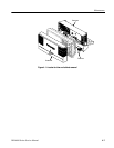
Follow these steps to remove the front case assembly. You must have previously
removed the Rear Case Assembly. See Figure 5--2 on page 5--6.
1. Pull off 14 knobs (2 large, 5 medium, 6 small, and 1 rotary).
2. Remove the front case by pulling back the board snaps and lifting the lower
right corner of the front case.
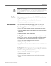
3. Place the oscilloscope face up on a soft surface (such as an anti-static mat),
with the bottom facing you.
4. Disconnect the bezel button flex circuit by gently pulling the flex circuit out
of the connector.
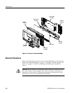
Follow these steps to remove the display module. You need to have previously
removed the rear case, power supply assembly, I/O board, and front case
assembly . Use a TORX T-15 screwdriver tip. See Figure 5--2 on page 5--6.
1. Disconnect the display power cable from the main board and the backlight
cable from the inverter board.
2. Remove the 4 screws that hold the display to the front chassis.
3. Gently lift the display up and off of the chassis.
CAUTION. Be careful when removing and reinstalling the Display module cables.
If the connectors have bent pins or are installed incorrectly; the Display may be
destr oyed.
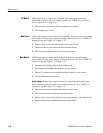
Follow these steps to remove the front panel module. You need to have
previously removed the front case assembly. Use a TORX T-15 screwdriver tip.
SeeFigure5--2onpage5--6.
1. Remove the 9 screws holding the front panel board to the chassis.
2. Lift the front panel board off of the chassis.
Front Case Assembly
Display
Front Panel