


Maintenance
DPO4000 Series Service M anual
4-9
CAUTION. To avoid damage to the front panel Standby/On switch assembly, do
not set the Display module assembly on a work surface. Sliding the oscilloscope
over the edge of the w ork surface could break off the On/Standby switch
assembly.
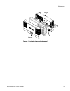
Follow these steps to remove the rear case. Use a TORX T-1 5 screwdriver tip.
SeeFigure5--1onpage5--4.
1. Remove the 4 screws from the back and sides of the rear case.
2. Grasp the case and pull outwards to remove it.
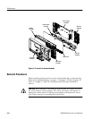
Follow these steps to remove the power supply module. You need to have
previously removed the rear case. Use a TORX T-15 screwdriver tip. See
Figure 5--4 on page 5--10.
1. Remove the 7 screws that secure the power supply module to the chassis.
2. Disconnect the power supply fan and connectors from the I/O board and the
main board.
3. Lift the power supply module off the chassis.
Power Supply Fan. Follow these steps to remove the power supply fan assembly.
You need to have previously removed the rear case and power supply assembly.
Use a TORX T-15 and a P2 screwdriver tip. See Figure 5--4 on page 5--10.
1. Remove the 5 screws that attach the power supply cover.
2. Lift the power supply cover off.
3. Use the P2 screwdriver tip and remove the 2 screws that attach the fan to the
cover.
Power Supply. Follow these steps to remove the power supply. You need to have
previously removed the rear case and power supply assembly. Use a TORX T-15
screwdriver tip. See F igure 5--4 on page 5--10.
1. Remove the 5 screws that attach the power supply cover.
2. Lift the power supply cover off.
3. Remove the 4 screws that attach the power supply to the power supply
bracket.
Rear C ase
Power Supply Module