


Maintenance
4-10
DPO4000 Series Service M anual
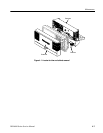
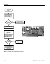
Follow these steps to remove the I/O board. You need to have previously
removed the rear case and power supply module. Use TOR X T-15 screwdriver
tip. See Figure 5--4 on page 5--10.
1. Remove the 5 screws that hold the I/O board to the chassis.
2. Lift straight up to remove.
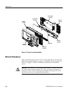
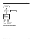
Follow these steps to remove the side fan assembly. You need to have previously
removed the rear case, power supply assembly, and I/O board. Use a TORX T-15
screwdriver tip. See F igure 5--5 on page 5--12.
1. Remove the 6 screws that hold the side fans to the chassis.
2. Disconnect the two fan connectors from the main board.
3. Slide the fan assembly out and away from the chassis.
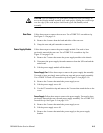
Follow these steps to remove the main board. You need to have previously
removed the rear case, power supply, I/O board, and side fans. Use a TORX T-15
screwdriver tip. See F igure 5--5 on page 5--12.
1. Disconnect the display cable from the main board.
2. Disconnect the backlight cable from the inverter board.
3. Remove 13 screws from the main board that connect it to the chassis.
4. Lift the main board up to remove.
Inverter board. Follow these steps to remove the inverter board from the main
board. You must have previously removed the main board. Use a TORX T-15
screwdriver tip. See F igure 5--5 on page 5--12.
1. Disconnect the inverter board cable from the main board.
2. Remove the inverter board from the plastic bracket.
3. Remove the 2 screws that hold the inverter board bracket to the main board.
4. Remove the inverter board bracket from the main board.
I/O Board
Main Fans
Main Board