


Camera interfaces
OSCAR Technical Manual V2.4.0
36
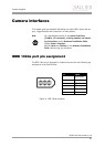
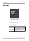
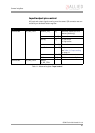
Camera I/O pin assignment
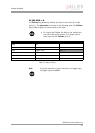
Figure 12: Camera I/O connector pin assignment
Note
L
GP = General Purpose
For a detailed description of the I/O connector and its oper-
ating instructions see the Hardware Installation Guide,
Chapter OSCAR input description.
Read all Notes and Cautions in the Hardware Installation
Guide, before using the I/O connector.
1
102
9
8
7
6
12113
4
5
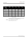
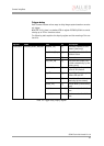
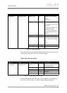
Pin Signal Direction Level Description
1 External GND GND for RS232 and
ext. power
External ground for RS232
and external power
2 External Power +8 ... +36 V DC Power supply
3
4 Camera In 1 In U
in
(high) = 2 V...U
inVCC
U
in
(low) = 0 V...0.8 V
Camera Input 1
(GPIn1)
default: Trigger
5
6 Camera Out 1 Out Open emitter Camera Output 1
(GPOut1)
default: IntEna
7 Camera In GND In Common GND for
inputs
Camera Common Input
Ground
(In GND)
8 RxD RS232 In RS232 Terminal Receive Data
9 TxD RS232 Out RS232 Terminal Transmit Data
10 Camera Out Power In Common VCC for
outputs
max. 36 V DC
Camera Output Power
for digital outputs
(OutVCC)
11 Camera In 2 In U
in
(high) = 2 V...U
inVCC
U
in
(low) = 0 V...0.8 V
Camera Input 2
(GPIn2)
default: -
12 Camera Out 2 Out Open emitter Camera Output 2
(GPOut2)
default: -