


Camera interfaces
OSCAR Technical Manual V2.4.0
47
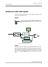
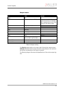
Output modes
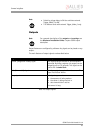
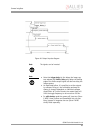
The Polarity setting refers to the input side of the optical coupler output.
PinState 0 switches off the output transistor and produces a low level over
the resistor connected from the output to ground.
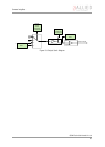
The following diagram illustrates the dependencies of the various output sig-
nals.
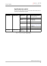
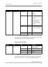
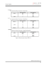
ID Mode Default
0x00 Off
0x01 Output state follows PinState bit Using this mode, the Polarity bit
has to be set to 0 (not inverted).
This is necessary for an error free
display of the output status.
0x02 Integration enable
Output 1
0x03 Reserved
0x04 Reserved
0x05 Reserved
0x06 FrameValid
0x07 Busy
Output 2
0x08 Follow corresponding input
(Inp1 Q Out1, Inp2 Q Out2, …)
0x09..0x0F Reserved
0x10..0x1F Reserved
Table 18: Output routing