


Description of the data path
OSCAR Technical Manual V2.4.0
52
Description of the data path
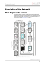
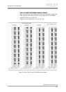
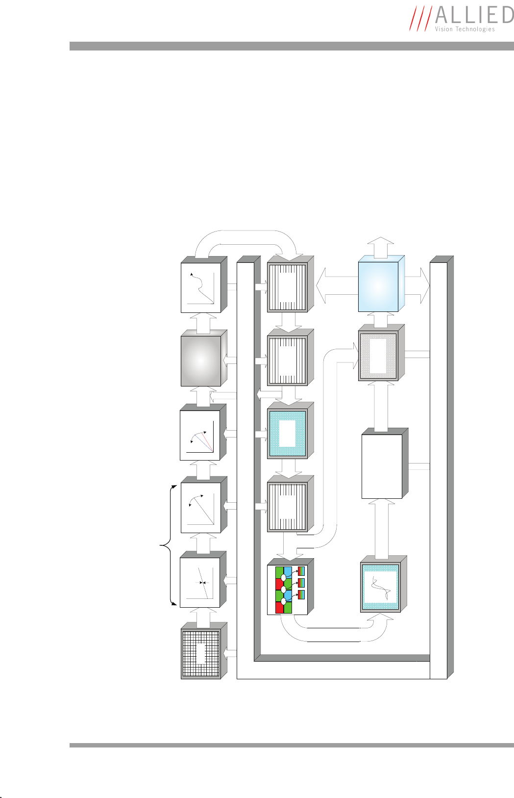
Block diagram of the cameras
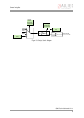
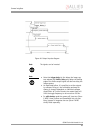
The following diagram illustrates the data flow and the bit resolution of
image data after being read from the CCD sensor chip in the camera. The indi-
vidual blocks are described in more detail in the following paragraphs. For
sensor data see Chapter Specifications on page 21.
Figure 20: Block diagram Oscar cameras
Sensor
Analog
Camera Control
HiRose I/O
RS232
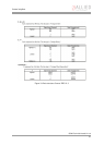
De-Bayering
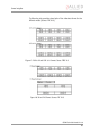
R1 G1 R2 G2
G3 B1 G4 B2
P
1
P
2
P
3
CCD: Analog Front End (AFE)
8/12 Bit
Test-Pattern
Auto-Data
10 Bit
8 Bit
Frame-
Memory
8/12
Bit
Graphics
Overlay
12 Bit
Horizontal
Mirror
12 Bit
Horizontal
Masking
Sharpness
Params
Camera Control
Offset
Analog
Gain
12 Bit
White Balance
12 Bit
Shading
Correction
12 Bit
LUT
12 Bit (LUT off)
8 Bit (LUT on)
10 Bit
Multiple Color
Operations
(RGB->YUV, Hue,
Saturation)
8 Bit
RAW-Mode
MUX
8/12
Bit
IEEE-1394
Interface
1394a