


8
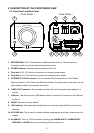
2. DESCRIPTION OF THE FRONT/REAR VIEW
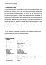
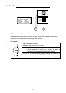
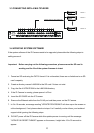
2.1 Front Panel and Rear Panel
-- Front Panel -- -- Rear Panel --
1
2
SD / SDHC
ETHERNET
(PoE)
AC 24V
DC 12V
VIDEO
USB
112
RESET
6
!
34 5
6
7
8
91011
1. MICROPHONE: The IP Camera has an additional audio function. The device has a
microphone built into its front panel which records sound.
2. POWER indicator: Indicates the power status of the unit.
3. Plug Inlet: A DC 12V inlet that connects to an external power supply.
4. Plug Inlet: An AC 24V inlet that connects to an external power supply.
5. ETHERNET 10/100 Connector: This is a standard RJ-45 connector for 10/100 Mbps
Ethernet networks. PoE (Power over Ethernet) function:
Provides power to the device via the
same cable as used for the network connection.
6. VIDEO OUT Connector: The connector provides the unit’s composite video signals to a
monitor.
7. USB port: The user can use a USB device cable to connect the IP camera to the USB port
on the PC.
8. RESET: Recover to factory default.
9. LED indicator: The green light indicates the unit is activating and the SD card cannot be
removed.
10. SD CARD slot: This is used for system software updating and archiving / accessing critical
images.
11. ALARM I/O: This is a 12-PIN connector including the ALARM IN/OUT, ALARM RESET,
GROUND and AUDIO items for connecting with external devices.