


AXIS Q1602 N etwork Camera
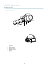
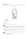
Hardware Overview
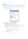
• Enabling the Focus A ssistant. Press and very quickly release the Control button.
• ConnectingtoanAXISVideoHostingSystemservice.See
page 38
. To connect, press and hold the button for about
1 second until the Status LED flashes green.
• ConnectingtoAXISInternetDynamicDNSService.See
page 38
. To connect, press and hold the button for
about 3 seconds.
• Resetting the product to factory default settings. See
page 45
.
Power connector - 2-pin terminal blo ck for power input.
I/O terminal connector - Use in applications for e.g. motion detection, eve nt triggering, time lapse recording and alarm notifications.
In addition to an auxiliary pow e r and a GND pin, the I/O terminal connector prov ides the interface to:
• Digital output – For connecting external devices such as relays and LEDs. Connected de vices can be activated by
the VAPIX® Application Prog ramm ing Interface, output buttons on the Live View page or by an Action Rule. The
output will show as active (shown under System Options > Ports & Devices) if the alarm device is activated.
• Digital input – An ala rm input for connecting de v ices that can toggle between an open and closed circuit, for
example: PIRs, door/window contacts, glass break detectors, etc. When a signal is received the state changes and
the input becom es active (shown under System Options > Ports & Devices).
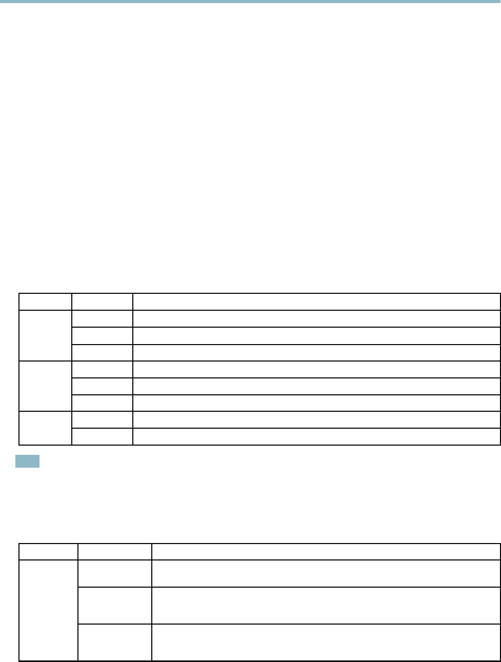
LED Indicators
LED
Color
Indication
Green
Steady for connection to a 100 MBit/s network. Flashes for netw ork activity.
Amber
Steady for connection to a 10 MBit/s network. Flashes for network activity.
Network
Unlit No network connection.
Green Steady g reen for normal operation.
Amber
Steady during startup and when restoring settings.
Status
Red
Slow flash for failed upgrade.
Green
Normal operation.
Power
Amber
Flashes green/amber during firmware upgrade.
Note
• The Status LED can b e configured to be unlit during normal operation. To configure, go to Setup > System O ptions >
Ports & Devices > LED. See the online help for more information.
• The Status LED can be confi gured to flash for identifying the unit. Go to Setup > System Options > Maintenance .
Status LED when using Focus Assistant
Status Color
I
ndication
Green
Focus Assistant is enabled
The lens is optim a lly adjusted
Amber The camera has been moved, or an object has be en inserted in front of the lens. Exit and
restart the Focus Assistant.
The lens is less optimally adjusted
Red The camera has been moved, or an object has be en inserted in front of the lens. Exit and
restart the Focus Assistant.
The lens is poorly adjusted
6