


6
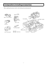
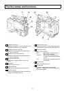
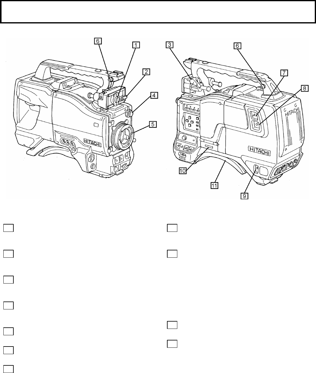
Facility names and functions
1
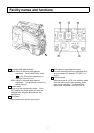
Viewfinder connector
Connect the accessory 1.5-inch viewfinder or the
separately sold GM-51 5-inch viewfinder.
2
Viewfinder horizontal lock lever
Secures the side to side position adjustment of
the 1.5-inch viewfinder.
3
Viewfinder front to rear lock screw
Secures the front to rear position adjustment of
the 1.5-inch viewfinder
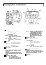
4
CC/ND filter select knob
Selects filter to match the light source of the
scene.
5
Lens mount
Bayonet type lens mount.
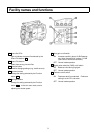
6
Shoulder belt hook
Attachment for separately sold shoulder belt.
7
Talk on/off switch
Intercom microphone on/off when connected into
a system with the RU-Z2/RU-Z1.
8
IIntercom level control
Intercom sound level (volume) adjustment when
connected into a system with the RU-Z2/RU-Z1.
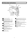
9
Power select switch
[BATT-CCU/VTR-EXT]
BATT : When power is supplied via the
BATT12V IN connector.
CCU/VTR : When power is supplied via the
connector for camera base station
or VTR.
EXT : When power is supplied via the DC
IN connector.
10
Setup card slot
Slot for inserting setup card.
11
Shoulder pad
Adjustable shoulder pad for comfortable
operation. Loosen the 2 screws and adjust the
front to rear position.