


69
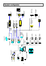
Studio system operation
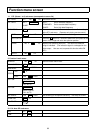
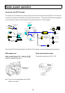
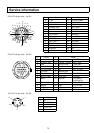
Auto setting with RU-Z2A / RU-Z1A (plug & play)s
No System Baud rate Audio level Video output Battery type
1
RU-Z1
62.5K( 1)
2
RU-Z2
9600( 1)
-20db( 1)
RGB
COMP
YC,
VBS ( 2)
12. 0V( 1)
( 3)
Self-contained
inner module operation
M-Z3B
(Betacam)
M-Z3P
(DVCPRO)
IM-Z3S
(BetaPRO)
3
IM-Z3J
(Digital-S)
62. 5K,
9600
AUTO( 4) AUTO( 4)
12. 0V
13. 2V
14.4V
4
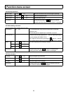
Self-contained
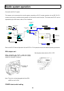
Camera adapter operation
CA-Z31/32
(portable VTR)
62.5K
9600
-60dB
-20dB
COMP
YC,
VBS,
RGB
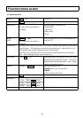
Notes:
1. When RU-Z1/Z2 (RC-Z1/Z2A) remote control is off, although settings can be changed at the camera head full menu, the I
nitial settings are returned at resupply of power.
2. When RU-Z1/Z2 (RC-Z1/Z2A) remote control is off, settings can be changed at the camera head full menu. Settings are
stored as common setting values in the RU-Z1/Z2 (RC-Z1/Z2A) memory.
3. With RU-Z1/Z2A, Alarm Set is fixed at 11.0 V.
4. When Auto is indicated, settings are automatic at the inner module.
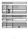
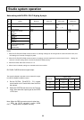
RU-Z2(RU-Z1)RGB connector signal output
The signals indicated in the table can be selected for output
from the RU-Z2(RU-Z1)RGB connector.
1.
Set the RC-Z2A / Z21A(RC-Z1 / Z11) remote
control switch to off. Control shifts from the RC to
the camera.
2.
Select the SYSTEM sub-menu from the Function
menu, then select the output signal at the VIDEO
<VTR> item.
Note: When the RBG connector output is other than
RGB, the RU-Z2 waveform monitor (WFM
OUT) display does not operate correctly.
Output signal
connector
RGB Component Y / C VBS
RRR-YC
G G Y Y VBS
BBB-Y