


10
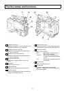
Facility names and functions
32
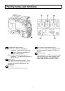
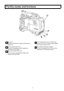
Video output connector (BNC)
Composite video signal output (1 Vp-p/75
Ω
).
33
Monitor output connector (BNC)
Video signal output for monitor (1 Vp-p/75
Ω
).
The same character signal as the viewfinder is
superimposed on the video signal to allow
checking the setting menu from the monitor
screen.
34
Genlock In connector (BNC)
Reference signal input for applying genlock to the
camera.
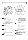
35
Remote control connector (4 pin)
Connection for RC-Z1, RC-Z11, RC-Z2A ,or
RC-Z21A camera remote control panel or a
personal computer.
36
Microphone connector (XLR, 3P)
Connection for separately sold microphone.
Microphone power is supplied from this
connector.
37
Lens connector (12 pin)
Connection for lens cable.
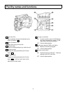
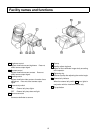
38
CCU/VTR connector (28 pin for CA-Z31, 26 pin
for CA-Z32) Use separately sold cable to connect
a portable VTR or RU-Z1/RU-Z2/camera base
station.
39
Lighting shoe screw hole (1/4-inch 20UNC)
40
Accessory shoe
A small spotlight can be attached without the light
striking the lens, viewfinder or microphone.
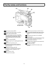
41
5-inch viewfinder attachment
The GM-51 5-inch viewfinder can be attached by
using the AT-30 adapter.
42
Mic holder screw hole
A separately sold MH-Z3 mic holder can be
attached.