


13
WARNING: DO NOT rock the counterweight shaft rigorously. Worm system damage due to
improperly gear mesh/slippage will not be covered by warranty.
WARNING: The new Gear Switch will allow you to achieve the most precise weight balance.
This also means the mount or OTA will swing FREELY when the Gear Switch is disengaged.
Always hold the OTA or mount when releasing Gear Switch or adjusting gear tension.
STEP 1. Removing the Mount from the Carrying Case
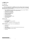
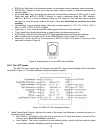
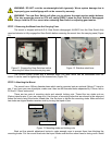
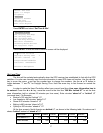
The mount is shipped with both R.A. Gear Switch disengaged. ALWAYS turn the Gear Switch fully
counterclockwise to fully engage the Gear Switch before removing the mount from the carrying case (Figure
11).
Figure 11. Engage the Gear Switches before
removing the mount from the carrying case
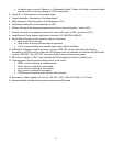
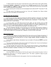
Figure 12. Stainless steel lever
The CEM60 mount comes with a stainless steel (SS) lever which can be unthreaded from the
mount. It can be used for tightening all the screws/nuts (Figure 12).
STEP 2. Attaching the Mount
The mount has a 150mm diameter base which can be mounted onto an optional iOptron 2” tripod or
pier. If you have your own tripod/pier, make sure it has two M8 threaded holes separated by 130mm, with a
Φ12mm X 15mm center stud.
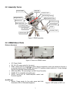
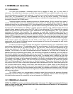
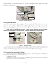
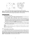
There are two sets of mounting studs and azimuth locking nuts. Thread the two studs onto an
iOptron tripod/or pier (if you are using one). Use the pair of mounting holes that are closest to the edge and
thread the studs using the shorter thread side. Use the lever to tighten the mounting studs. Make sure that
two studs are aligned eastern-western side by turning the tripod or pier.
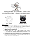
Figure 13. Mounting studs and locking nuts
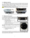
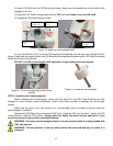
Back out the azimuth adjustment knobs to make enough room to prevent them from blocking the
mounting knobs. Put the mount head onto the tripod. Make sure that the mount head is facing north. Install
Mounting studs
Azimuth locking nuts