


14
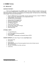
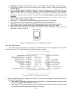
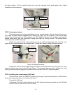
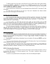
the Nylon washer. Put the azimuth locking nuts onto the mounting studs, hand tighten them. Adjust
tripod/pier to level the mount.
Figure 14. Attaching the mount
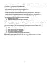
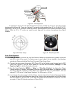
STEP 3. Setting the Latitude
This step requires you to know the latitude of your current location. This can be found from your
8407 hand controller after the embedded GPS receives the signal from the satellites. It also can be easily
found on the Internet, with your GPS navigator or a GPS capable cell phone. You will have to change this
latitude setting every time you significantly change your night sky viewing location. This setting directly
affects the mount’s GOTO accuracy.
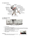
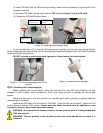
Slightly loosen the Latitude Locking Clamps. Turn the Latitude Adjustment Knob until the arrow
points to your current latitude on the Latitude Scale. Tighten the Latitude Locking Clamps when done.
Figure 15. Setting the latitude
At this point, with the mount leveled and pointed north, and the latitude set, the Polar Axis (R.A. axis)
should be pointing very close to the NCP and Polaris. This alignment accuracy will be sufficient for visual
tracking and short duration piggy-back (camera mounted on top of the OTA) astrophotography.
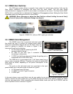
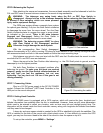
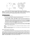
STEP 4. Installing the Counterweight (CW) Shaft
There are three screws on CEM60 CW Mounting Housing: A Shaft Locking Screw, a Shaft Position
Screw on the other side and a Low-Latitude Set Screw.
To install the CW shaft
(1) Remove CW Shaft Locking Screw from the CW Mounting Housing and back out the CW Shaft
Position Screw to make room for the CW shaft;
Latitude
locking clamp
Latitude
Adjustment
knob
Mounting stud
Azimuth adjustment
knob
Nylon washer