


16
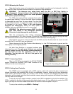
STEP 6.Balancing the Payload
After attaching the scope and accessories, the mount head assembly must be balanced in both the
R.A. and DEC axes to ensure minimum stress on the mount driving mechanism.
WARNING: The telescope may swing freely when the R.A. or DEC Gear Switch is
disengaged. Always hold on to the telescope assembly before releasing the Gear Switches
to prevent it from swinging, which can cause personal
injury and/or equipment damage.
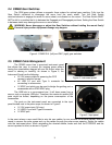
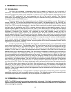
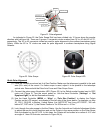
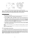
The CEM gear system utilizes a magnetic force system
for optimal gear meshing. Fully turn the Gear Switch clockwise
to disengage the worm from the worm wheel. Turn the Gear
Switch counterclockwise to engage the worm to worm wheel,
as indicated on the mount. There is NO state between
Engaged and Disengaged. Setting the Gear Switch in
between states may damage the worm or worm wheel.
WARNING: The balancing process MUST be done
with Gear Switch at the Disengaged position!
Otherwise it might damage the worm system.
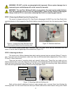
With the corresponding Gear Switch disengaged,
balance the assembly in R.A. axis by moving CW along its shaft. Balance in DEC axis by moving the scope
with accessories back and forth in the mount saddle or within the scope mounting rings.
Only balance one axis at a time and start with the DEC axis first. Double check the mount to make
sure both the R.A. and DEC axes are balanced.
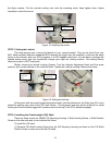
Return the mount to the Zero Position after balancing; i.e., the CW Shaft points to ground, and the
telescope tip is at its highest position.
Set both Gear Switches to engaged positions after
balancing the mount. To make sure the gears are meshed
properly, gently turn the Gear Switch counterclockwise all
the way until you feel the resistance, but not over
tightening. You may back out 1//8 turn if the gear is not
moving smoothly.
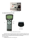
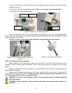
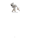
STEP 7. Connecting Cables
Plug in a 12V DC power supply to the DC12V POWER
socket. Connect the Go2Nova
®
8407 Hand Controller to the
HBX port on the mount side panel.
STEP 8. Setting Hand Controller
The CEM60 mount is equipped with a GPS receiver, which will receive the time, longitude and
latitude information from satellites after the link is established. However, there are still some parameters
which need to be entered to reflect your location, such as time zone info and daylight saving time. The
information will be stored inside the hand controller memory along with longitude and latitude coordinates
until they need to be changed.
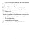
A clear sky and open space outside is needed for the GPS to establish its link with the satellites. The
GPS is installed on the side of the mount with a black plastic cover. If it has difficulty to receive the GPS
signal, you may turn the mount head to the side of the mount to clear the space on top of it.
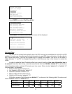
To set up the controller, press MENU =>“Settings”:
Figure 19. Gear switches
Gear switch
Figure 20. Connecting the cables