


8
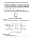
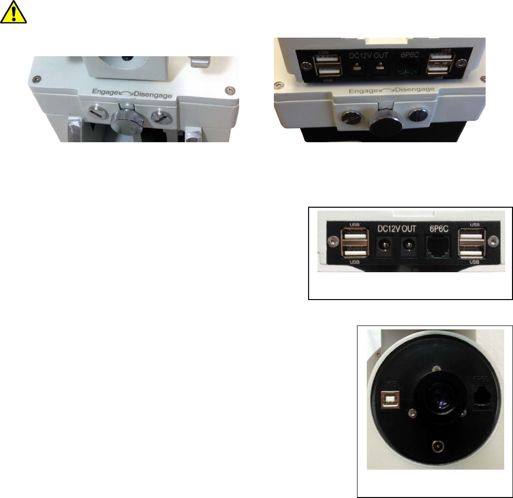
2.4. CEM60 Gear Switches
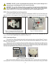
The CEM gear system utilizes a magnetic force system for optimal gear meshing. Fully turn the
Gear Switch clockwise to disengage the worm from the worm wheel. Turn the Gear Switch
counterclockwise to engage the worm to worm wheel, as indicated on the mount. The Gear Switch MUST
NOT be left in a position that is in between the Engaged and Disengaged positions. Setting the Gear Switch
in between states may damage the worm or worm wheel.
WARNING: Never disengage or adjust the Gear Switches without holding the mount firmly!
Personal injury and/or equipment damage may happen.
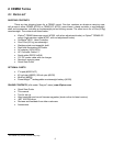
Figure 4. CEM60 R.A. (left) and DEC (right) gear switches
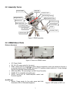
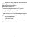
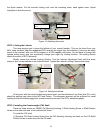
2.5. CEM60 Cable Management
The CEM60 mount has a pre-wired instrument panel
that allows the user to connect his imaging gears without
having the wires/cables dragged all over the mount when the
mount is slewing or tracking. As shown in Figure 5, the
Instrument Panel has the following:
2X 12V power outlets for powering the CCD
camera or electric focuser
4X USB 2.0 port with Type A connector for
connecting to accessories.
1X 6P6C port which can be used to bridge the guiding port or
accessories with a 6P6C/6P4C plug
The USB hub is a non-powered one. It will draw power from a
source, such a computer USB port. Therefore, the maximum usable USB
ports might be limited, depending on the power consumption of the
accessories.
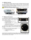
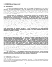
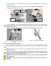
The ports on the instrument panel are connected to the input
panel located next to the polar scope, as shown in Figure 6.
1X 12V power input (5A max.)
1X USB 2.0 port with Type B connector
1X 6P6C port
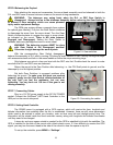
In the event where a user would like to wire his own cables, he can remove the dovetail saddle. Next he
needs to remove the polar scope and run the cables through the polar scope opening. Solder the cables
onto the instrument pane. When reinstalling the dovetail saddle, make sure that the STOPPER and the
arrow is pointed to front, as shown in Figure 7.
Figure 5. Instrument panel
Figure 6. Input panel