


19
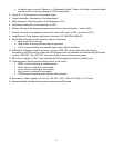
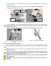
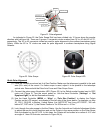
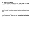
Figure 21. Polar alignment
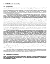
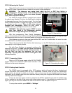
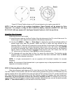
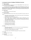
As indicated in Figure 22, the Polar Scope Dial has been divided into 12 hours along the angular
direction with half-hour tics. There are 2 groups, 6 concentric circles marked from 36’ to 44’ and 60’ to 70’,
respectively. The 36’ to 44’ concentric circles are used for polar alignment in the northern hemisphere using
Polaris. While the 60’ to 70’ circles are used for polar alignment in southern hemisphere using Sigma
Octantis.
Figure 22. Polar Scope
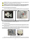
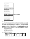
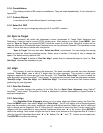
Figure 23. Polar Scope LED
Quick Polar Alignment
(1) Level the CEM60 mount and set it at Zero Position. Make sure the telescope is parallel to the pole
axis (R.A. axis) of the mount. If a finder scope is used, adjust it to be parallel to the telescope
optical axis. Remove both the Polar Axis Cover and Polar Scope Cover.
(2) Connect the polar scope illumination LED (Figure 23) to the Reticle socket located next to DEC
motor unit (Figure 3). Turn the mount power on. Use the Hand Controller (“Settings” => “Set
Eyepiece Light”) to set the illumination intensity.
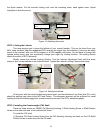
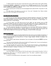
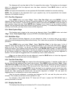
(3) Use the Hand Controller (MENU => “Align” => “Pole Star Position”) to display the Polaris
Position on the LCD screen, as indicated in the left side of the figure below. For example, on May
30, 2010, 20:00:00 in Boston, United States (Lat N42º30’32” and Long W71º08’50”, 300 min
behind UT, DST set to Y), the Polaris Position is 1hr 26.8m and r = 41.5m.
(4) Look through the polar scope to find the Polaris. Use the Azimuth and Latitude Adjustment Knobs
to adjust the mount in both directions and put the Polaris in the same position on the Polar Scope
Dial as indicated on the HC LCD. In this case, the Polaris will be located at a radius of 41.5’ and
an angle of 1 hour 26.8 minute, as shown In Figure 24 (b).
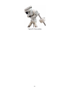
DECdriveunit
Polaraxiscover
Polarscopecover
Az.adj.knob
Az.Lockingnut
Lat.lockingclamp
Polaraxis
Lat.adj.knob