


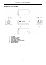
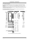
CV-M4
+
/M4
+
CL, CV-M7
+
/M7
+
CL
- 11 -
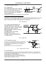
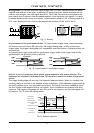
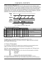
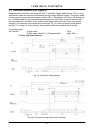
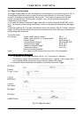
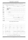
Restart Continuous Trigger mode. RCT.
The RCT mode makes it possible to use a lens with video controlled iris for intelligent traffic
surveillance applications, ITS. The camera is running continuously, and the iris is controlled from
the iris video output. When a trigger pulse is applied, the scanning is reset, the previous signal is
dumped with a fast dump read out, and the new triggered exposure is started. This fast dump
read out takes 133 H (5,23 msec. and it has the same effect as “smearless read out”. Smear over
highlighted areas are reduced for the triggered frame. In edge pre-select mode (TR=1), the RCT
mode (RC=1) can be activated. RCT cannot be selected by switch settings.
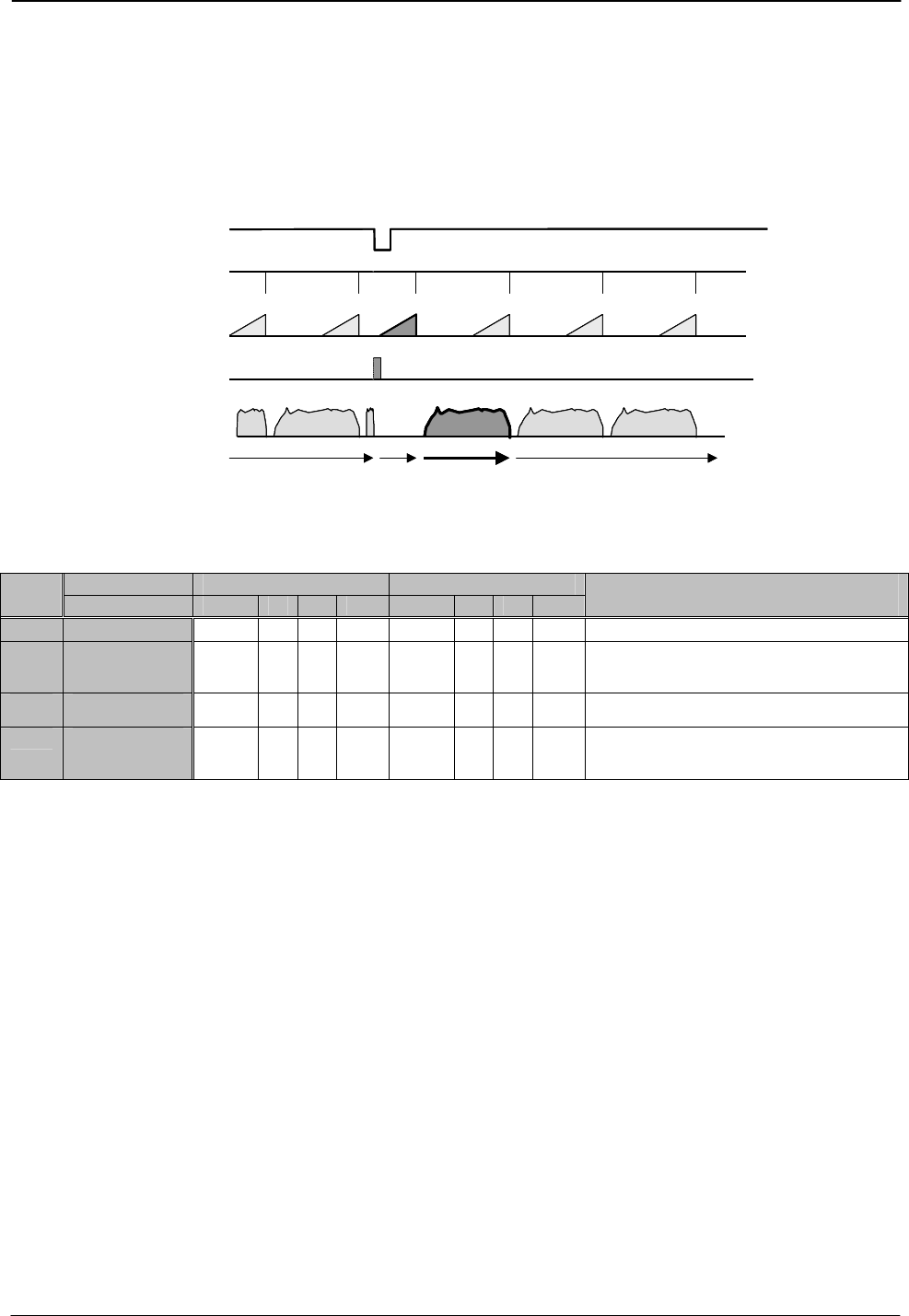
Trigger
SG
Exposure
Video out
Dump
Read out
Continuous video out Continuous video outTriggered
Frame
Trigger
SG
Exposure
Video out
Dump
Read out
Continuous video out Continuous video outTriggered
Frame
Fig. 15. Restart Continuous Trigger mode.
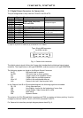
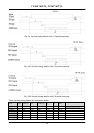
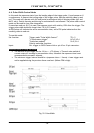
Trigger modes with possible functions
Scanning Full scanning Partial scanning
TR=
*) Binning norm. v norm v
Remarks
0 Normal
√ √
√
n
SH= , PE= for shutter select
1 Edge Pre-
select
√ √
√
n
SH= , PE= for shutter select
SL= , Smearless active
RC=1 for Restart Continuous Trigger mode
2 Pulse Width
√ √
√
n
SL= , Smearless active
3 Fr. Delay
read out
√ √
√
n
SH= , PE= for shutter select
ML= , Multi shutter active
SL= , Smearless active
*) Binning will only work √ Allowed and described mode
for CV-M4
+
and CV-M4CL
+
n Non-allowed.
All trigger modes can be H synchronous or H a-synchronous. (HC=0, HC=1)
In Edge Pre-select mode (TR=1), the Restart Continuous Trigger mode can be activated
(RC=1) by RS-232C and CL only.
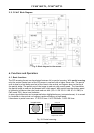
6.2. Output of Timing Signals
It is not possible to synchronize the camera from an external sync source except by extern
trigger. The camera will always run with its internal X-tal controlled timing.
The CV-M4
+
camera is designed for easy interfacing to frame grabbers with LVDS signal levels
(EIA64), or with Camera Link interface.
To synchronize the video data transfer from the camera the following signals are available:
FEN Frame enable
LEN Line enable
PCLK Pixel clock
DVAL
EEN Exposure enable. (Low during active exposure).
See the full connector pin assignment for LVDS a Camera Link in chapter 5.2 and 5.3.
For complete documentation on the Camera Link standard, please contact your JAI distributor.