


CV-M4
+
/M4
+
CL, CV-M7
+
/M7
+
CL
- 7 -
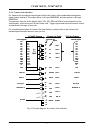
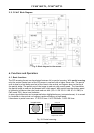
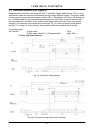
5.4.5. Camera Link interface
For Camera Link the digital output signals follow the Camera Link standardized multiplexed
signal output interface. The output driver is NS type DS90CR283, and the receiver is NS type
DS90CR284.
The data bits from the 10 bit digital video, FEN, LEN. EEN and DVAL are multiplexed into the
twisted pairs, which are a part of the Camera Link. Trigger signals and the serial camera control
is feed directly through its own pair.
For a detailed description of Camera Link specifications, please refer to the Camera Link
standard specifications found on www.jai.com
1
14
13
26
X0
X1
X2
X3
Xclk
SerTFG
SerTC
CC1
CC2
CC3
CC4
Sheilds
4 x
7-1
MUX
D0
D1
D2
D3
D4
D5
D6
D7
D8
D9
EEN
LEN
FEN
DVAL
nc
Pclk
In 0
In 1
In 2
In 3
In 4
In 6
In 27
In 5
In 7
In 8
In 23
In 24
In 25
In 26
In (nx)
Txclk
15
2
16
3
17
4
19
6
18
5
21
8
7
20
22
9
10
23
24
11
12
25
Pair 1
Pair 2
Pair 3
Pair 5
Pair 4
Pair 7
Pair 6
Pair 8
Pair 9
Pair 11
Pair 12
Sheilds
TXD out
RXD in
Ext. trig in
Ground
Signal
Connector pin
CV-M4CL Camera
D0
D1
D2
D3
D4
D5
D6
D7
D8
D9
EEN
LEN
FEN
DVAL
nc
Pclk
TXD out
RXD in
Ext. trig in
Camera Link Cable
Camera Signals
Camera Signals
To Frame Grabber
Multi Shut. in Multi Shut. in
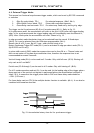
Fig. 8. Principle diagram for Camera Link interface