


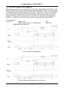
CV-M4
+
/M4
+
CL, CV-M7
+
/M7
+
CL
- 4 -
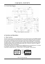
5. Pin Assignment
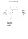
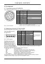
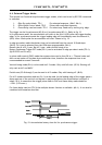
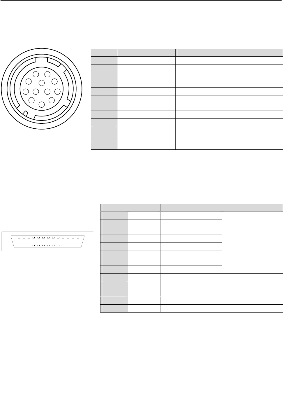
5.1. 12-pin Multi-connector (DC-IN/RS232C)
Type: HR10A-10R-12PB-01 (Hirose) male. (Seen from rear of camera.)
3
4
5
6
7
8
9
10
11
12
1
2
*) Iris video out without sync. Refer to 5.4.1 video output
*1) EEN or c. sync out select by RS232C command SE
Fig. 2. 12-pin connector.
*2) input on 12-pin con. or LVDS/(CL) by command TP or int. SW301-1
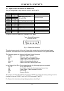
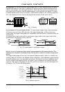
5.2. Digital Output Connector for EIA-644 (LVDS)
This pin configuration is only valid for CV-M4
+
/ CV-M7
+
Type: 26 pin MRD connector
3M 10226-1A10JL
Fig. 3. LVDS connector
The digital input and output
signals follow the EIA 644
standard. It is also called Low
Voltage Differential Signal
(LVDS). The output differential
line driver is NS type DS90C031.
*1) input on 12-pin con. or LVDS/(CL) by command TP or int. SW301-1
Pin no. Signal Remarks
1 GND
2 +12 V DC input
3 GND
4 Video output
Analogue video for test and iris control *)
5 GND
6 RXD in
7 TXD out
Or via Camera Link for CL
+
versions
if JP 301 short
8 GND
9 EEN/sync out
*1) composite sync.
10 Trigger input
*2) Or on LVDS or Camera Link.
11 Multi shutter
*2) Or on LVDS or Camera Link.
12 GND
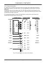
Pin no. Signal Function Remarks
1 14 +/- D2 Video output (LSB)
2 15 +/- D3 Video output
2 16 +/- D4 Video output
4 17 +/- D5 Video output
5 18 +/- D6 Video output
6 19 +/- D7 Video output
7 20 +/- D8 Video output
8 21 +/- D9 Video output (MSB)
8 most significant bits
of the 10 bit digitized
video
9 22 +/-TRIG Trigger input
*1) or TTL on #10 12 pin
10 23 +/-Multi Multiple exposure
*1) or TTL on #11 12 pin
11 24 +/-LEN Line enable
12 25 +/-FEN Frame enable
13 26 +/-PCLK Pixel clock
13
14
1
26
Line receiver is NS type DS90C032.
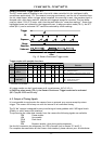
The following signal are found on the Digital Output Connector:
D2 – D9 8 bit video Data out.
PCLK Pixel CLocK. One clock pulse for each video data byte.
LEN Line ENable. A pulse for the beginning of each new line.
FEN Frame Enable. Video frame out data is valid.
Multi Multiple shutter. Trigger input for multiple exposures.
Ext. Trigger IN External trigger signal in for exposure control.
The polarity for LEN, FEN, TRIG is negative and Multi is positive as factory setting. It can be
changed by internal SW301-2 and 3 or RS 232C command FP and TP