


CV-M2
- 17 -
6.3. Input/Output of Timing Signals
6.3.1. Input of Timing Signals
It is not possible to synchronize the camera from an external sync source except by an extern
trigger pulse. The camera will always run with its internal X-tal controlled timing.
Trigger input through Camera Link. TI=0
Trigger input as TTL on pin #10 on 12 pin Hirose. TI=1
The trigger polarity is active low. TP=0
Trigger input can be changed to active high. TP=1
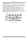
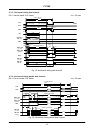
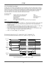
6.3.2. Output of Timing Signals
To synchronize the video data transfer from the camera the following signals are available in a
base configuration of Camera Link:
FVAL Frame valid High for valid Frame
LVAL Line valid High for valid line
PCLK Pixel clock Rising for data stobe
DVAL Data valid High for valid data
EEN Exposure enable Low during exposure.
(Not specified by CL).
See the full connector pin assignment for Camera Link in chapter 5.3 and 5.4.5
For complete documentation on the Camera Link standard, please contact your JAI distributor.
EEN is also found as a TTL signal on pin #9 on the 12 pin Hirose. EEN is low during exposure.
6.4. Trigger Modes
This camera can operate in 6 primary modes. 1 non-triggered mode and 5 external trigger
modes, which can be set by RS-232C commands.
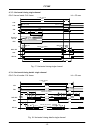
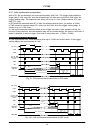
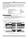
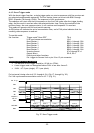
1. Normal continuous Mode. TR=0 Pre-selected exposure. (SM=0, SM=1)
2. Edge Pre-select Mode. TR=1 Pre-selected exposure. (SM=0, SM=1)
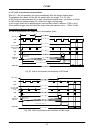
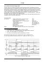
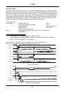
3. Restart Continuous Trigger Mode. TR=2 Pre-selected exposure. (SM=0, SM=1)
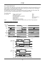
4. Pulse Width Control Mode. TR=3 Pulse width controlled exposure.
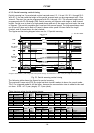
5. Burst Trigger mode Mode. TR=4 5 EPS. Read out by trailing trig. edge.
6. PIV Mode. TR=5
In normal continuous mode and edge pre-select mode the shutter time can be selected from the
normal 10 fixed steps. (SM=0). Or it can be selected from the 1216 steps programmable (SM=1).
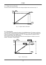
Pulse width control can be used for long time exposure. The trigger pulse width can be from 2
LVAL to ∞. The exposure time is not recommended to exceed 2 seconds.
Partial scan (SC=0 through 3) can be used in all 6 modes.
Important note on changing trigger modes by RS-232C and CL.
Disconnect or stop the trigger input before changing mode by RS-232C or Camera Link. In worst
case it can lead to latch-up of camera function and communication if a mode command is
received at same time as a trigger pulse. The modes are trigger modes (TR) and scanning (SC).
The camera latch-up can only be reset if the power is switched off and on again.