


CV-M2
- 4 -
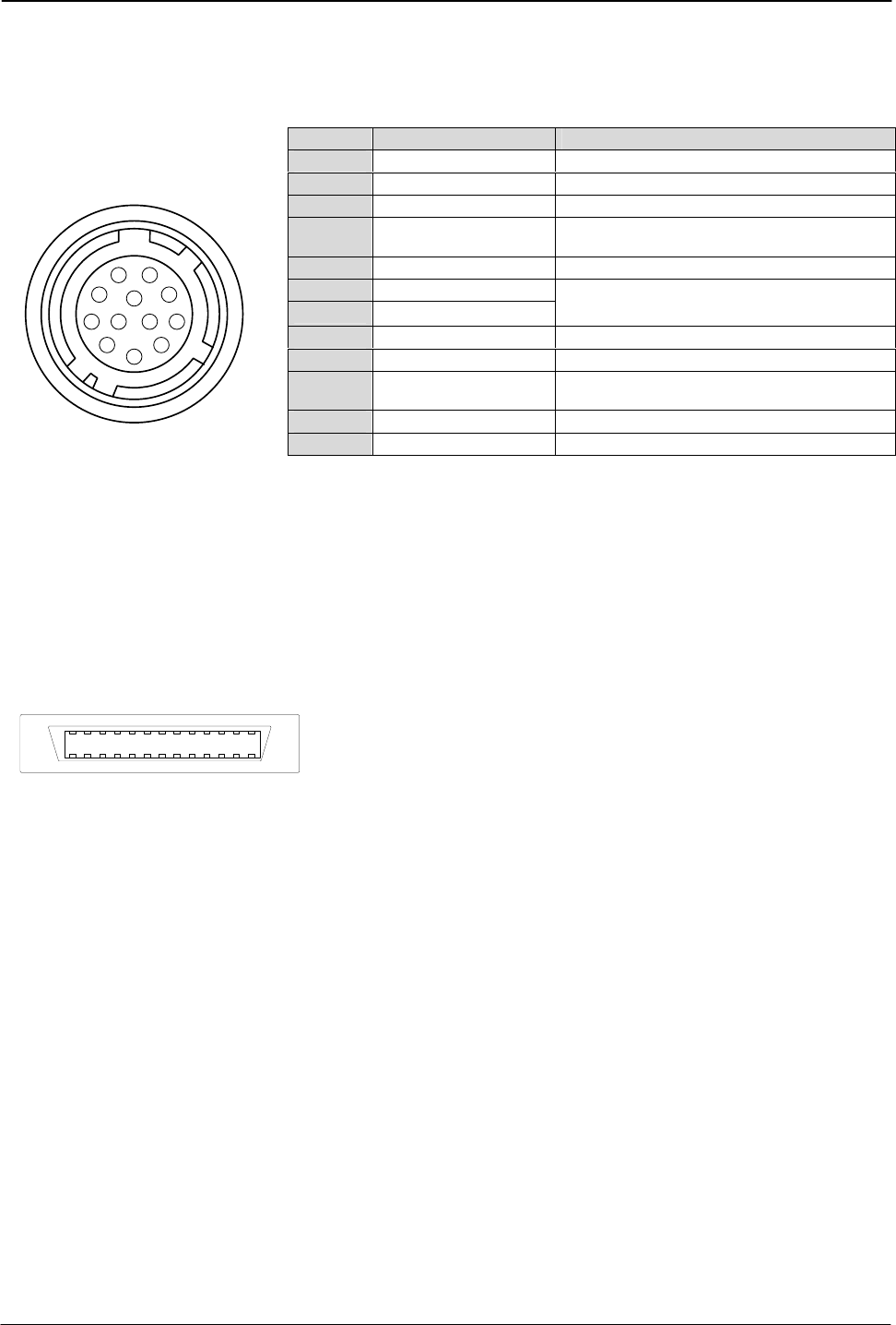
5. Pin Assignment
5.1. 12-pin Multi-connector (DC-IN/Trigger)
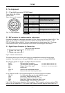
Type: HR10A-10R-12PB-01
Pin no. Signal Remarks
1 GND
2 +12 V DC input
3 GND
4 Iris Video output
Analogue video for iris control in
continuous mode and RCT mode. *)
5 GND
6 RXD in
7 TXD out
RS 232C. Or via Camera Link
By internal switch HR/CL (Refer to 7.2)
8 GND
9 EEN out
Or via Camera Link
10 Trigger/SG input
TI=1. (Or via Camera Link if TI=0 )
SG=0 trigger input. SG=1 sensor gate contr.
11 Factory use
For factory test
12 GND
(Hirose) male.
(Seen from rear of camera.)
3
4
5
6
7
8
9
10
11
12
1
2
Fig. 2. 12-pin connector.
*) Refer to 5.4.2. for Iris video output. SG = Sensor Gate Control.
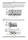
5.2. BNC connector for analogue monitor video output
On the BNC connector an analogue video signal (CCIR or EIA) for monitoring is found if OS=2. The
signal can be viewed on a standard monitor as 50 FPS/15.734 kHz 290 lines if MN=1, or 60
FPS/15.734 kHz 240 lines if MN=0. It is non-interlaced and for single channel only. The image
covers the full format, but the resolution is much lower than the digital video output.
5.3. Digital Output Connector for Camera Link
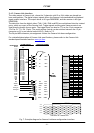
Type: 26 pin MRD connector
13
14
1
26
3M 10226-1A10JL
Fig. 3. Camera Link connector
The digital output signals follow the Camera Link standardized multiplexed signal output
interface. The output driver is NS type DS90CR285, and the receiver is NS type DS90CR286.
The following signals are found on the Digital Output Connector:
SerTC RXD serial data to camera
(Int. switch HR/CL. Refer to 7.2)
SerTFG TXD serial data to frame grabber
(Int. switch HR/CL. Refer to 7.2)
CC1 Trigger/Sensor Gate input
(TI=0 for CL. SG=1 for Sensor Gate)
CC2 Factory use
X0 to X3 Camera Link multiplexed data out
Xclk Camera Link clock. Used as pixel clock.
In the Channel Link X0 to X3 multiplexed signals the following signals are encoded.
D0 – D9 2 x 10 bit video data out for right and left channel.
LVAL Line VALid. Video line data is valid.
FVAL Frame VALid. Video frame data is valid.
DVAL Data VALid. Effective video pixel data is valid
EEN Exposure ENable.
(Not specified by Camera Link).
LVAL, FVAL, DVAL polarity is positive. EEN is negative. TRIG is negative as factory setting. TRIG
polarity can be changed by TP. For Camera Link interface principle diagram please check Fig. 7.