


CV-M2
- 24 -
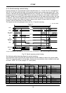
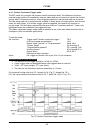
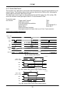
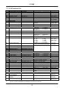
6.4.7. Sensor Gate Control
This function is for applications with strobe flash illuminations or long time accumulations up to
several frames. The resulting video is then read out after the first FVAL (or SG), following the
trailing edge of the Sensor Gate Control signal.
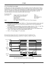
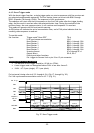
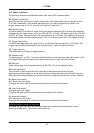
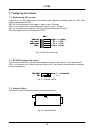
The sensor gate control signal can be synchronized by the FVAL signal. Fig. 29A. and fig. 29B.
shows the minimum sensor gate signal width if it is synchronized to FVAL.
To use this mode:
Set function: Trigger mode “Normal” TR=0
Sensor gate control SG=1
LVAL synchronous accumulation LS=1
Scanning format SC=0 through SC=4
Output select OS=0, OS=1
Polarity and other functions
Input: Sensor gate control to Camera Link or pin 10 on 12-pin connector.
Important notes on using this mode.
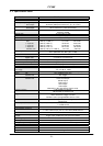
LVAL
DAT A OUT
SUB
SG
FVAL
SG di sabl e
EEN
Exposur e
Per i od
Sensor Gat e
Con t r ol
Si gnal
al ways Low
al ways Hi gh
No Da t a
Fig. 29. Sensor Gate Control
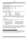
FVAL
SG
514ck
444ck
LVAL
78ck
(1.95us)
Sensor Gat e
Cont r ol Si gnal
608ck
1282ck
(1ck=25ns)
82ck
(2.05us)
( 15. 2us)
( 32. 05us)
Fig. 29A. Sensor Gate Control single channel details
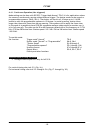
FVAL
SG
514ck
LVAL
80ck
(2us)
Sensor Gat e
Cont r ol Si gnal
190ck
864ck
(1ck=25ns)
32ck
80ck
(2us)
(4.75us)
( 21. 6us)
Fig. 29B. Sensor Gate Control dual channel details