


CV-M2
- 21 -
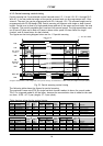
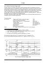
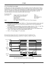
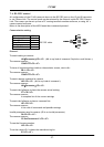
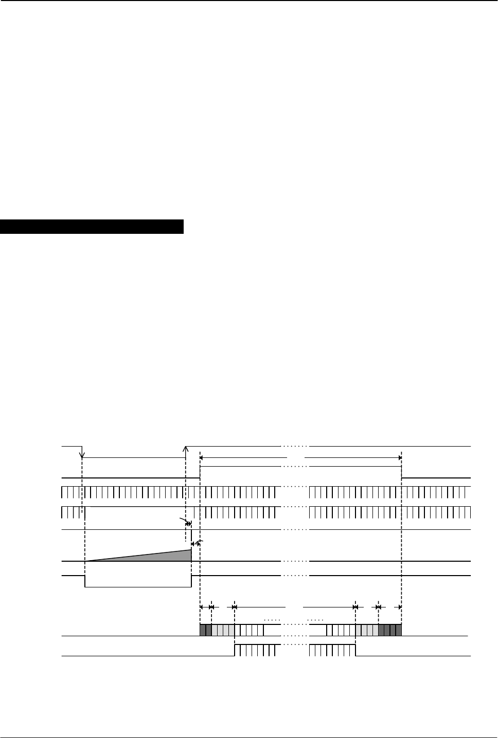
6.4.4. Pulse Width Control Mode
In PWC mode, the trigger leading edge will start an exposure at the first LVAL pulse if LS=0 (or
immediately if LS=1). It stops at the trailing edge of the trigger pulse, and the resulting video is
read out. This mode will operate with full and partial scanning. An EEN pulse will indicate the
active accumulation time, and a FVAL pulse indicates that the resulting video is read out.
Long time exposure can be done with pulse width control mode.
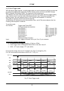
To use this mode:
Set function: Trigger mode “Pulse width control” TR=3
LVAL synchronous accumulation LS=0, LS=1
Scanning format SC=0 through SC=4
Output select OS=0, OS=1
Polarity and other functions
Input: Ext. trigger to Camera Link or pin 10 on 12-pin connector.
Important notes on using this mode.
• The duration of the trigger can be >2LVAL to ∞. Thermal noise and dark current noise will
increase by accumulation time, therefore the exposure time is not recommended to
exceed 2 seconds.
• If LS=0 (Synchronous accumulation), the minimum trigger interval is 1 FVAL + 3 LVAL. The
new exposure should not be finished before the previous frame is read out.
• If LS=1 (Asynchronous accumulation) the minimum trigger interval is the exposure time +
3 LVAL. A new trigger must not be applied before FVAL is low.
• 1LVAL = 47.9 µsec (single). 27.3 µsec (dual).
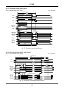
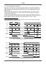
For horizontal timing refer to 6.2.3. through 6.2.6. (Fig.17. through fig. 20.)
For LVAL synchronous accumulation refer to 6.2.7 and 6.2.8. (Fig. 21. fig. 22.)
LVAL
DV A L
DA TA OUT
SUB
SG
FVAL
OB
1
Ef f ect i ve Li nes
2L
2345
1
1
9
7
1
1
9
6
1
1
9
8
1
2
0
0
1
1
9
9
1200L
4L
1214L
EEN
Ext . Tr i g 1
4L
Res e
r
v
e
d
4L
OB
R
eser v
e
d
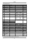
t2
Exposur e
Pe r i o d
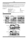
When t he LVAL Sync Accum. : t1=0.5 to 1.5L, t2=1.5L
When t he LVAL Async Accum. : t 1=0. 5L, t 2=0. 5 t o 1. 5L
t1
Fig. 26. Pulse Width Control mode vertical timing