


CV-M2
- 26 -
7. Configuring the Camera
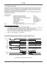
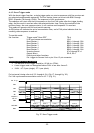
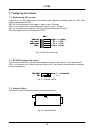
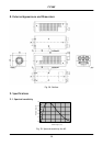
7.1. Mode setting SW1 on rear
Switch SW 1.1 on the camera rear can be used to select digital or analogue video out. SW1.1 has
higher priority than RS-232C.
SW1.2 is for termination of the trigger 1 input on pin #10 Hirose.
(SW1.3 is for termination of the factory test input on pin #11 Hirose)
SW1.4 is for master gain selection. SW1.4 has higher priority than RS-232C.
Fine gain adjustment on R channel by RS-232C.
Gain
1
2
3
4
Trig 1 term.
Video out
RS-232 < > potm.
Digital < > Analog
TTL < > 75Ω
SW 1
Factory use
TTL < > 75Ω
Gain
1
2
3
4
Trig 1 term.
Video out
RS-232 < > potm.
Digital < > Analog
TTL < > 75Ω
SW 1
Factory use
TTL < > 75Ω
Fig. 30. SW1 on camera rear
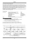
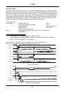
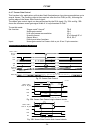
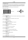
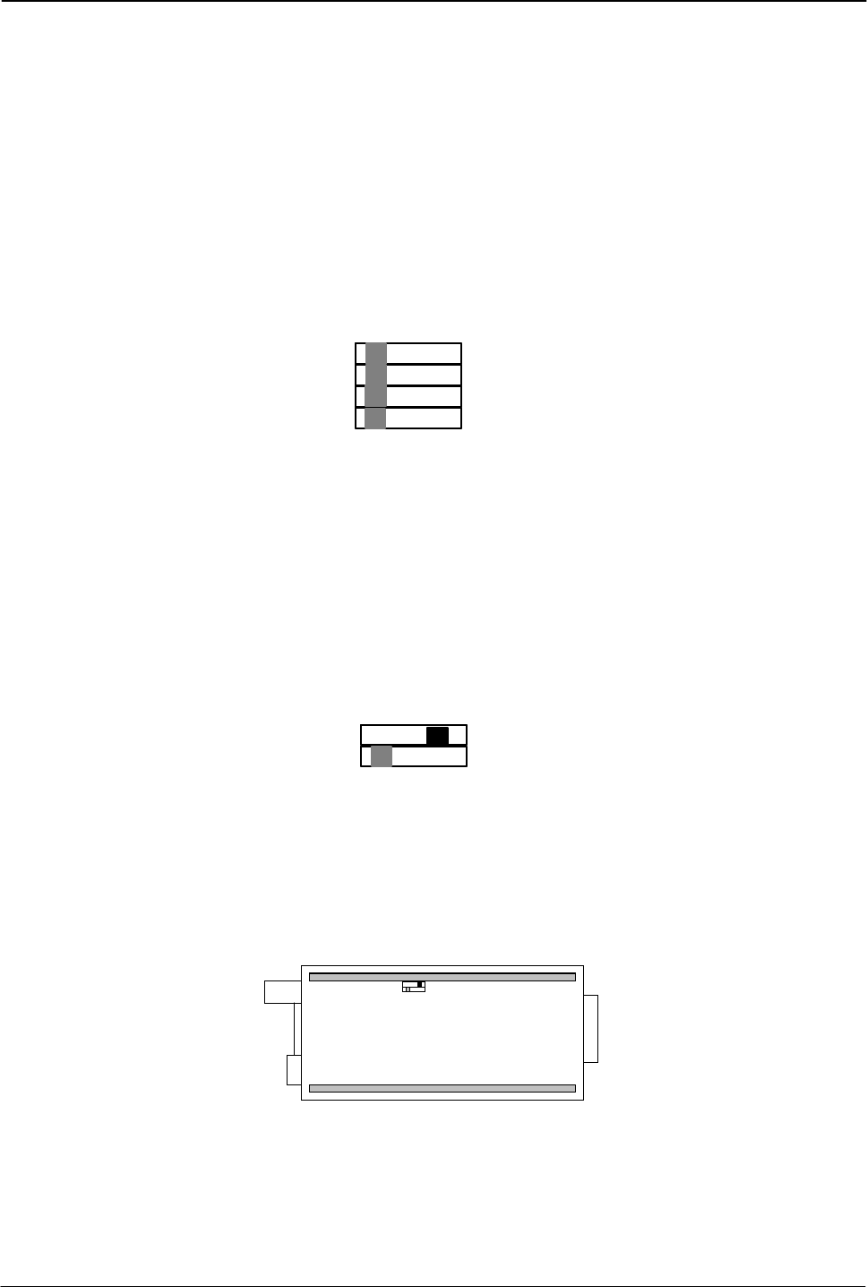
7.2. RS-232C/Camera Link switch
The internal switch HR/CL can be used to select the control input via the 12 pin Hirose as RS-
232C or via Camera Link. Factory setting is Camera Link. The switch is placed inside the camera
on the motherboard.
1
2
Hirose < > Camera Link
< >
RS- 232C
NC
1
2
Hirose < > Camera Link
< >
RS- 232C
NC
Fig. 31. Internal Switch
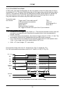
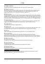
7.3. Internal Switch
The switch is placed inside the camera on the motherboard.
SWSW
Fig. 32. Internal switch