


CV-M2
- 7 -
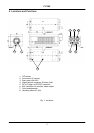
6. Functions and Operations
In the following the format shown in “7.5. CV-M2 command list” are used for function
commands and parameters.
6.1. Basic functions
The M2 camera is a progressive scan camera with 10 or 8 bit video output in single or dual
channel Camera Link. On a BNC connector a standard composite video output CCIR or EIA for
monitor use is found. The image covers the full format, but the resolution is much lower than
the digital video output.
An iris video signal can be used for lens iris control if the camera is in continuous mode or Reset
Continuous Trigger mode.
A knee function (and gamma for single channel) makes it possible to cover high contrast scenes.
The CV-M2 camera has 1/2, 1/4 or 1/8 partial scanning. Programmable partial scan, where the
start line and the number of lines can be selected in 1line increments is also available.
There are 5 trigger modes. Normal continuous, reset continuous trigger, edge pre-select, pulse
width control, edge pre-select burst trigger and PIV trigger. (PIV, Particle Image Velocimety).
The Sensor Gate Control can be used in normal continuous mode together with strobe flash.
The accumulation can be LVAL synchronous or LVAL a-synchronous.
In the following some of the functions are shown in details.
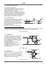
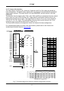
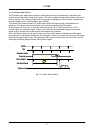
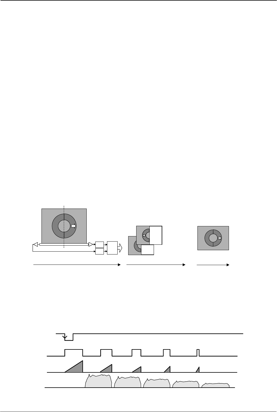
6.1.1. Dual video output
The video read out through Camera Link can be via a single or via double channels. (OS=0 for
single channel, OS=1 for dual channel.) If dual video outputs are used, the frame grabber PC
should reconstruct the image frame from the 2 half images.
A/D
A/D
RL
Camera Link
Interface
2 x 10 bit
Image
Reconstructed
image on display
The two half images
are stored in separate
memory locations
.
CV-M2 Camera Frame Grabber
Display
R
L
The mirrord half
image R is reversed
and stiched together
with the half image L
A/D
A/D
RL
Camera Link
Interface
2 x 10 bit
Image
Reconstructed
image on display
The two half images
are stored in separate
memory locations
.
CV-M2 Camera Frame Grabber
Display
R
L
The mirrord half
image R is reversed
and stiched together
with the half image L
Fig. 8. Dual channel read out
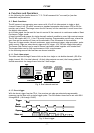
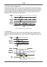
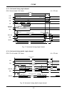
6.1.2. Burst trigger
With the burst trigger function TR=4, five previous set edge pre-selected programmable
exposures can be done with a single trigger pulse. The five shutter times can be set with BSH1
through BSH5. (1H through 1216H.)
Trigger
Exposure
Video out
Burst
Shutter
1 2345
1 234 5
Frame
Trigger
Exposure
Video out
Burst
Shutter
1 2345
1 234 5
Frame
Fig. 9. Burst trigger